Digital LogicsUnit 28 min read
Boolean Algebra & Logic Gates: Laws, Minimization, Gates & Latches
Unit 2 of Digital Logics covers Boolean algebra laws, logic gate symbols, truth tables, simplification techniques (algebraic and K-map), and fundamental sequential elements (SR, JK, D, T latches/flip-flops) with real-world applications in digital systems.
Boolean Algebra Fundamentals
1. Definitions and Basic Laws
Boolean algebra is a mathematical system for manipulating binary variables (0 and 1) using logical operations. It forms the foundation for designing digital circuits.
Key Laws (Visualized in Truth Tables)
| Law | Expression | Truth Table (A=0,1) |
|---|---|---|
| Commutative | A + B = B + A | |
| A · B = B · A | ||
| Associative | (A + B) + C = A + (B + C) | |
| (A · B) · C = A · (B · C) | ||
| Distributive | A + (B · C) = (A + B) · (A + C) | |
| Identity | A + 0 = A | |
| A · 1 = A | ||
| Complement | A + A' = 1 | |
| A · A' = 0 | ||
| Idempotent | A + A = A | |
| A · A = A | ||
| Absorption | A + (A · B) = A | |
| A · (A + B) = A |
Worked Example: Simplify . Solution:
- Apply Distributive Law to : .
- Simplify using Idempotent Law (): .
- Expand : .
- Apply Idempotent Law (): .
- Factor from terms: .
- Since , simplify to: .
In the Real World
eSewa (Nepal):
- Boolean Logic in Payment Validation:
When you pay via eSewa, the system checks multiple conditions (e.g.,
account_balance > amount,OTP_matched,network_available) using AND/OR gates in hardware to approve/reject transactions. Example:Transaction_Approved = (Balance_OK AND OTP_Valid) OR (Admin_Override).
- Boolean Logic in Payment Validation:
When you pay via eSewa, the system checks multiple conditions (e.g.,
Khalti’s Fraud Detection:
- Uses Boolean expressions to flag suspicious transactions. For example:
Fraud_Alert = (Amount > Threshold) AND (Location_Change) AND (Time_Window_Violation).
- Uses Boolean expressions to flag suspicious transactions. For example:
NTC’s Traffic Light Control:
- Traffic lights use sequential logic (flip-flops) to cycle through states (Red → Green → Yellow). The timing is controlled by Boolean conditions like:
Green_Light = NOT (Pedestrian_Button_Pressed) AND (Current_State = Green).
- Traffic lights use sequential logic (flip-flops) to cycle through states (Red → Green → Yellow). The timing is controlled by Boolean conditions like:
2. Logic Gates and Their Symbols
Logic gates are physical implementations of Boolean operations. Below are their standard symbols and truth tables.
Basic Gates
| AND Gate (A·B) | OR Gate (A+B) | NOT Gate (A') |
|---|---|---|
| A | B | A·B |
| 0 | 0 | 0 |
| 0 | 1 | 0 |
| 1 | 0 | 0 |
| 1 | 1 | 1 |
Universal Gates (NAND and NOR)
- NAND Gate: Output is
0only if all inputs are1. - NOR Gate: Output is
1only if all inputs are0. - Why Universal? Any Boolean function can be implemented using only NAND or only NOR gates.
Example: Implement using NAND gates only. Solution:
- Rewrite using De Morgan’s Law: '.
- Implement using NAND gates as shown below:
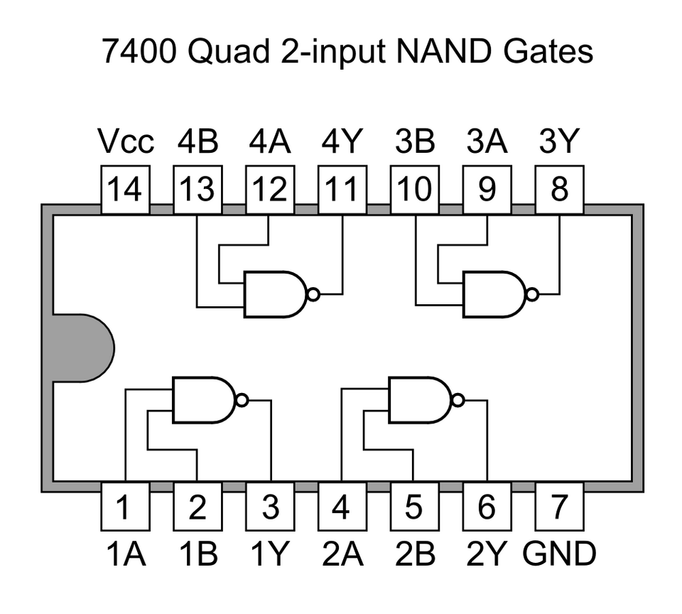 NAND Gate IC (7400 Series) (Image: Tosaka, CC BY 3.0, via Wikimedia Commons)
```mermaid
flowchart LR
  A["A"] --> N1["NAND"]
  B["B"] --> N1
  N1 --> N2["NAND"]
  C["C"] --> N2
  N2 --> F["F = AB + C"]
3. Boolean Function Minimization
A. Algebraic Minimization
Use Boolean laws to simplify expressions. Example: Simplify . Solution:
- Group terms with common literals: .
- Factor: .
- Simplify : .
- Factor : .
- Since : .
- Factor : .
Result: (simplified to a single input!).
B. K-Map Minimization (Visual Grouping)
Karnaugh Maps (K-maps) provide a graphical method to minimize Boolean functions.
Example: 4-Variable K-Map
Minimize with don’t-cares .
| AB\CD | 00 | 01 | 11 | 10 | |
|---|---|---|---|---|---|
| 0 | 1 | d | d | 1 | |
| 1 | 1 | d | d | 1 | |
| ---- | ---- | ---- | ---- | ||
| 0 | 1 | d | d | 1 | |
| 1 | 1 | d | d | 1 |
Steps:
- Group 8-cell blocks (powers of 2):
- Group 1: Cells
0,2,8,10→ . - Group 2: Cells
4,6,12,14→ .
- Group 1: Cells
- Don’t-cares can be used to complete groups (e.g., cell
1is unused but adjacent to0and2). - Final Expression: .
Implementation with Universal Gates: Use NAND gates to implement and , then combine with a NAND as OR.
4. Sequential Logic: Latches and Flip-Flops
Sequential circuits store state (memory) using latches or flip-flops.
A. SR Latch (Basic Memory Element)
| S (Set) | R (Reset) | Q (Output) | Q' (Complement) |
|---|---|---|---|
| 0 | 0 | Hold | Hold |
| 0 | 1 | 0 | 1 |
| 1 | 0 | 1 | 0 |
| 1 | 1 | Invalid | Invalid |
Problem: Invalid state when . Solution: Use JK or D flip-flops.
Real Picture:
B. Flip-Flops (Edge-Triggered)
Flip-flops are clocked versions of latches, avoiding invalid states.
| Flip-Flop | Inputs | Output Update | Use Case |
|---|---|---|---|
| SR | S, R | Level-triggered | Basic memory |
| JK | J, K, Clock | Edge-triggered | Counters, registers |
| D | D, Clock | Stores input at clock edge | Shift registers |
| T | T, Clock | Toggles on clock edge | Divide-by-2 counters |
Example: JK Flip-Flop as T Flip-Flop Connect . On each clock pulse, the output toggles:
- .
Application in Pathao’s Ride Allocation: Pathao uses flip-flops in counters to track ride requests in real-time. For example:
- A binary counter (made of T flip-flops) increments with each new request.
- When the counter reaches a threshold (e.g., 100), it triggers a load balancer to assign drivers.
Exam Tip
For Boolean Algebra:
- Always show step-by-step simplification using laws (e.g., distributive, absorption).
- Draw truth tables for functions with 3+ variables to verify correctness.
For K-Maps:
- Group in powers of 2 (1, 2, 4, 8 cells).
- Use don’t-cares to complete larger groups (e.g., a 4-cell group).
- Label groups clearly (e.g., ).
For Gates/Latches:
- Draw standard symbols (not text-based).
- Compare SR latch vs. flip-flops in exams (e.g., "Why is a JK flip-flop better than an SR latch?").
- Memorize universal gate implementations (NAND/NOR for any function).
Real-World Links:
- eSewa/Khalti: Boolean conditions for transactions.
- NTC Traffic Lights: Sequential logic for timing.
- Pathao/Daraz: Counters for request tracking.
Final Note: Master K-maps and flip-flop behavior—these are high-weightage topics in TU/PU exams. Practice designing circuits from Boolean expressions and vice versa.
Based on the TU BIT syllabus for Digital Logics (BIT103), unit 2.
Discussion
Loading…