Systems Analysis and DesignUnit 45 min read
Design Principles, Techniques & Tools
Unit 4 of Systems Analysis and Design covers system design fundamentals, including design principles (modularity, coupling, cohesion), design techniques (DFD, ERD, UML), user interface design, and prototyping tools, with real-world applications in Nepalese software and business systems.
Key Concepts in System Design
1. Design Principles
Design principles guide developers in creating efficient, maintainable, and scalable systems. The three core principles are:
- Modularity: Breaking a system into smaller, independent modules (e.g., login module, payment module).
- Coupling: Measures how tightly modules depend on each other (low coupling = better).
- Cohesion: Measures how focused a module is (high cohesion = better).
classDiagram
    class Module {
        +High Cohesion
        +Low Coupling
    }
    class System {
        <<composite>>
        +Modular Design
    }
    System "1" *-- "many" Module : contains
Why it matters?
- Modularity helps in reusing code (e.g., a login module used in multiple apps).
- Low coupling makes systems easier to update (e.g., changing a payment gateway without breaking the whole app).
- High cohesion improves readability and debugging (e.g., a single module handling all user authentication).
Real-world example:
- eSewa uses modular design for its payment system. The payment module is separate from the user profile module, allowing updates without disrupting the entire app.
2. Design Techniques
Design techniques help visualize and document system requirements before coding.
A. Data Flow Diagrams (DFD)
A DFD shows how data moves through a system. It includes:
- Processes (P): Actions performed (e.g., "Process Order").
- Data Stores (D): Databases or files (e.g., "Customer Database").
- Data Flows (F): Movement of data (e.g., "Order → Payment").
- External Entities (E): Users or systems outside (e.g., "Customer").
flowchart TD
    E1["Customer"] -->|"Place Order"| P1["Process Order"]
    P1 -->|"Save to DB"| D1["Order Database"]
    P1 -->|"Send Receipt"| E2["Email System"]
Example:
- Pathao’s ride-hailing system uses a DFD to show how a user request flows from the app to the driver assignment system.
B. Entity-Relationship Diagrams (ERD)
An ERD models database structure by showing:
- Entities (e.g., "Customer", "Order").
- Relationships (e.g., "Customer places Order").
- Attributes (e.g., "Customer(ID, Name, Email)").
erDiagram
    Customer ||--o{ Order : places
    Customer {
        int ID
        string Name
        string Email
    }
    Order {
        int OrderID
        date OrderDate
    }
Example:
- Daraz’s inventory system uses an ERD to track products, orders, and suppliers efficiently.
C. Unified Modeling Language (UML)
UML provides 14 diagram types, but the most used in design are:
- Use Case Diagram – Shows user interactions (e.g., "User logs in").
- Class Diagram – Defines classes and relationships (e.g., "Customer → Order").
- Sequence Diagram – Shows message flow between objects (e.g., "User → Server → Database").
sequenceDiagram
    User->>Server: Login Request
    Server->>Database: Verify Credentials
    Database-->>Server: Credentials Valid
    Server-->>User: Login Success
Example:
- Khalti’s payment system uses a sequence diagram to show how a transaction is processed from user to bank.
3. User Interface (UI) Design
A good UI ensures usability, accessibility, and aesthetics. Key principles:
- Consistency: Same buttons/layouts across screens.
- Feedback: Confirmation messages (e.g., "Order placed!").
- Navigation: Clear menus and search bars.
Example:
- NTC’s online bill payment portal follows consistent UI design so users can easily navigate between services.
4. Prototyping Tools
Prototyping helps visualize and test designs before full development. Common tools:
| Tool | Purpose | Example Use Case |
|---|---|---|
| Figma | Wireframing & UI design | Designing eSewa’s mobile app |
| Adobe XD | Interactive prototypes | Prototyping Pathao’s driver app |
| Balsamiq | Low-fidelity wireframes | Quick mockups for Nepal Rastra Bank |
Example:
- Nepal Stock Exchange (NEPSE) used Figma to prototype its trading platform before full development.
In the Real World
eSewa’s Payment System
- Uses modular design (separate modules for login, payment, and receipt).
- DFD helps track how money flows from user to bank.
- UML sequence diagrams show transaction steps.
Pathao’s Ride-Hailing App
- ERD manages drivers, users, and ride history.
- Low-coupling design allows updates (e.g., adding a new payment method) without breaking the app.
Daraz’s Order Processing
- DFD shows how an order moves from cart to delivery.
- Prototyping in Figma helped test the UI before launch.
Exam Tip
- DFDs & ERDs are highly tested – practice drawing them from scenarios.
- UML diagrams (especially use case & sequence) appear in short-answer questions.
- Design principles (modularity, coupling, cohesion) are often asked in theory questions.
- Real-world examples (eSewa, Khalti, Daraz) can be used to explain concepts in exams.
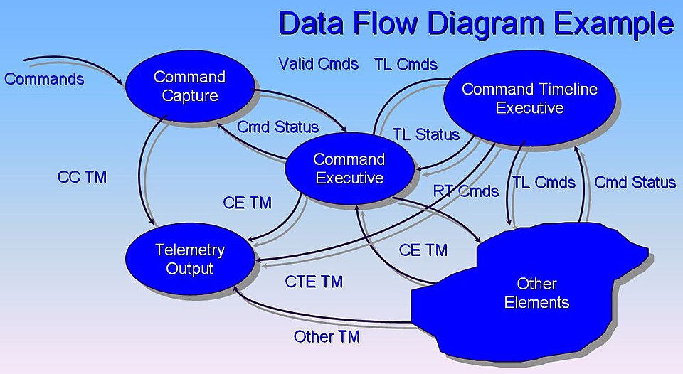 A standard DFD showing processes, data flows, and external entities. (Image: John Azzolini, Public domain, via Wikimedia Commons)
Based on the TU BIT syllabus for Systems Analysis and Design (BIT253), unit 4.
Discussion
Loading…