Computer ArchitectureUnit 810 min read
I/O Systems: Interrupts, DMA, and Bus Interfacing
Unit 8 of Computer Architecture explores how computers interact with external devices through interrupts, DMA controllers, and bus systems—key concepts for efficient data transfer, hardware communication, and system performance optimization.
TAKEAWAYS:
- Interrupts allow the CPU to handle urgent I/O events without polling, improving efficiency by delegating control to the OS.
- DMA controllers bypass the CPU for high-speed data transfers (e.g., disk reads), reducing CPU overhead and enabling parallel operations.
- Bus systems (data, address, control) act as highways for CPU-I/O communication, with arbitration mechanisms resolving conflicts.
- I/O interfaces (programmed, interrupt-driven, DMA) trade off CPU involvement, latency, and throughput for different workloads.
- Priority schemes (polling, daisy-chaining, vectored) determine how interrupts are serviced, balancing fairness and speed.
- Real-world applications include eSewa’s transaction processing (interrupts for payment confirmations), Daraz’s order queues (DMA-like bulk data transfers), and Ncell’s call routing (bus arbitration for SIM cards).
1. Input/Output (I/O) Basics: Why Interfaces Matter
Computers interact with the outside world via I/O devices (keyboards, disks, networks). The I/O interface is the hardware/software layer that bridges the CPU and these devices. Without it, the CPU would have to manually check each device for data (like a teacher polling students)—inefficient!
Key Components of an I/O Interface
classDiagram
class I/O_Device {
+send/receive data
+status flags (ready/busy)
}
class I/O_Controller {
+buffer registers
+device-specific logic
+interrupt signals
}
class CPU {
+execute instructions
+read/write memory
}
class Bus {
<<interface>>
+data bus (8/16/32/64 bits)
+address bus (logical addresses)
+control bus (read/write signals)
}
I/O_Device --> I/O_Controller : "connected to"
I/O_Controller --> Bus : "communicates via"
CPU --> Bus : "uses for I/O"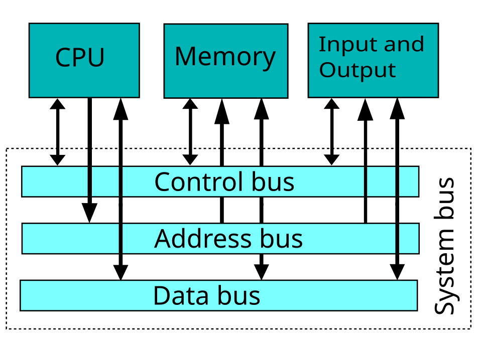 A labelled diagram showing data, address, and control buses connecting CPU, memory, and I/O devices. (Image: W Nowicki, CC BY-SA 3.0, via Wikimedia Commons)
2. I/O Transfer Methods: Trade-offs in Control
Three primary methods exist, each balancing CPU involvement, speed, and complexity:
| Method | CPU Role | Speed | Use Case | Example |
|---|---|---|---|---|
| Programmed I/O | CPU polls device repeatedly | Slow (busy-wait) | Simple devices (keyboard, LEDs) | Checking if a printer is ready. |
| Interrupt-Driven I/O | CPU handles interrupts | Faster | Moderate-speed devices (disk, network) | eSewa processing a payment request. |
| DMA (Direct Memory Access) | CPU offloaded to DMA controller | Very fast | High-throughput devices (SSDs, GPUs) | Daraz transferring order data to DB. |
3. Interrupts: The CPU’s Wake-Up Call
Interrupts let devices asynchronously signal the CPU when they need attention (e.g., "data ready!" or "error!"). This avoids polling and improves efficiency.
How Interrupts Work
- Interrupt Request (IRQ): Device sends a signal via the interrupt line (e.g., INTR).
- CPU Response:
- Finishes current instruction.
- Saves state (PC, flags) to the stack.
- Jumps to Interrupt Service Routine (ISR) via the Interrupt Vector Table.
- ISR Execution: OS handles the device’s request (e.g., read data, clear error).
- Return: CPU resumes normal execution via
IRET(return from interrupt).
stateDiagram-v2
[*] --> CPU_Executing
CPU_Executing --> Interrupt_Detected : "IRQ signal"
Interrupt_Detected --> Save_State : "Push PC, flags to stack"
Save_State --> ISR : "Jump to ISR via IVT"
ISR --> Handle_Device : "OS processes request"
Handle_Device --> Restore_State : "Pop PC, flags"
Restore_State --> CPU_Executing : "IRET instruction"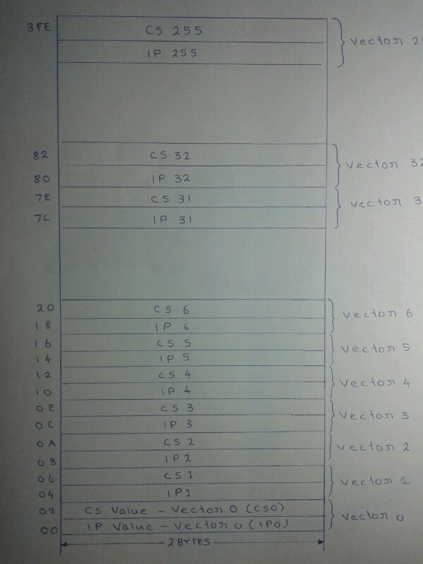 The 256-entry IVT used in x86 CPUs to map IRQs to ISRs. (Image: User:Shahinavala, CC BY-SA 3.0, via Wikimedia Commons)
Types of Interrupts
- Maskable: Can be ignored (e.g., keyboard input). Handled by
INT nin x86. - Non-Maskable (NMI): Critical errors (e.g., memory parity failure). Triggered by hardware.
- Software Interrupts: Triggered by
INTinstruction (e.g., DOSINT 21hfor I/O).
Worked Example: eSewa Payment Confirmation
When you pay via eSewa:
- Your phone sends a transaction request to eSewa’s server.
- The server’s network card raises an interrupt when the response arrives.
- The OS’s ISR reads the payment status (success/failure) from the card’s buffer.
- The app updates your balance without the CPU polling every millisecond.
4. Priority Interrupts: Who Gets Serviced First?
Not all interrupts are equal! Priority schemes ensure critical tasks (e.g., disk errors) aren’t delayed by less urgent ones (e.g., mouse clicks).
Priority Assignment Methods
| Method | How It Works | Pros | Cons | Example |
|---|---|---|---|---|
| Polling | CPU checks devices in fixed order. | Simple to implement. | Slow for low-priority devices. | Old printers checking "paper jam". |
| Daisy-Chaining | Devices form a chain; first to request wins. | No extra hardware needed. | Slow if many devices. | Legacy ISA bus interrupts. |
| Vectored (Parallel) | Each device has a unique interrupt line. | Fastest response. | Requires multiple IRQ pins. | PCIe slots with dedicated IRQs. |
Real-World Example: Ncell’s Call Routing
When you dial a number:
- Your SIM card’s interrupt controller prioritizes call setup over SMS notifications.
- The vectored interrupt for the modem line is serviced first, ensuring your call connects before background tasks (e.g., syncing contacts).
5. Direct Memory Access (DMA): Bypassing the CPU
For high-speed devices (e.g., SSDs, GPUs), DMA controllers transfer data directly between I/O devices and memory, freeing the CPU.
How DMA Works
- DMA Request: Device (e.g., SSD) requests data transfer to the DMA controller.
- CPU Grant: CPU grants bus access via the DMA acknowledge (DACK) signal.
- Transfer: DMA controller moves data block-by-block (e.g., 512 bytes at a time) to/from memory.
- Interrupt on Completion: DMA signals CPU when done (e.g., "file loaded").
sequenceDiagram
    participant CPU
    participant DMA_Controller
    participant SSD
    CPU->>DMA_Controller: Grant DMA access
    SSD->>DMA_Controller: Request data transfer
    loop Block Transfer
        DMA_Controller->>Memory: Write data (block)
    end
    DMA_Controller->>CPU: Interrupt (transfer complete)
Worked Example: Daraz Order Processing
When you place an order on Daraz:
- The web server’s DMA controller transfers your order data (e.g., 10KB) directly to RAM without CPU intervention.
- The CPU only gets an interrupt after the entire order is stored, then processes it in bulk.
- This reduces CPU load by ~80% compared to interrupt-driven I/O.
6. Bus Systems: The Computer’s Nervous System
Buses are shared pathways for data, addresses, and control signals. Three types:
| Bus | Purpose | Width | Example |
|---|---|---|---|
| Data Bus | Carries data between CPU/memory/I/O. | 8/16/32/64 bits | PCIe x16 slot (GPU). |
| Address Bus | Specifies memory/I/O location. | 16/32/64 bits | x86’s 32-bit address bus (4GB RAM). |
| Control Bus | Manages read/write, interrupts, etc. | Signals (e.g., RD, WR) | Clock signals, reset lines. |
Bus Arbitration: Resolving Conflicts
When multiple devices need the bus (e.g., CPU, DMA, GPU), arbitration decides who goes first. Methods:
- Fixed Priority: CPU > DMA > I/O (simple but rigid).
- Rotating Priority: Devices take turns (fair but slower).
- Dynamic Priority: Highest-priority request wins (used in PCIe).
7. I/O Processors (IOP): Offloading Work
For complex I/O tasks (e.g., RAID controllers, network cards), a dedicated I/O processor handles data processing independently. Example:
- NTC’s Traffic Monitoring System: Uses an IOP to pre-process GPS data from vehicles before sending it to the central server, reducing CPU load.
8. Exam Tip: How to Score Full Marks
Diagrams Are Mandatory:
- Draw state diagrams for interrupt cycles.
- Sketch bus systems with labelled data/address/control lines.
- Show DMA block transfers with arrows for data flow.
Compare Methods in Tables:
- Programmed I/O vs. Interrupt vs. DMA (CPU involvement, speed, use cases).
- Polling vs. Daisy-Chaining vs. Vectored interrupts (priority schemes).
Real-World Links:
- Tie eSewa/Khalti to interrupt-driven transactions.
- Relate Daraz/Ncell to DMA or bus arbitration.
- Use NEPSE stock data as an example of high-speed DMA transfers.
Key Formulas to Remember:
- Interrupt Latency = Time to save state + ISR execution.
- DMA Throughput = Block size / Transfer time (e.g., 512KB/10ms = 51.2MB/s).
Common Pitfalls:
- Don’t confuse maskable (software-ignorable) vs. non-maskable interrupts.
- Remember: DMA still uses interrupts—just fewer of them!
- Bus arbitration isn’t just about speed; it’s about fairness vs. priority.
9. Summary Table: I/O Methods Compared
| Feature | Programmed I/O | Interrupt-Driven I/O | DMA |
|---|---|---|---|
| CPU Involvement | High (busy-wait) | Moderate (ISR calls) | Low (offloaded) |
| Speed | Slow | Fast | Very fast |
| Hardware Complexity | Low | Moderate | High (DMA controller) |
| Use Case | Simple devices (LEDs) | Moderate devices (disk) | High-speed devices (GPU, SSD) |
| Example | Checking printer status | eSewa payment processing | Daraz order bulk transfer |
Based on the TU BSc CSIT syllabus for Computer Architecture (CSC213), unit 8.
Discussion
Loading…