Microprocessor Based DesignUnit 410 min read
8051 Architecture, Programming & Applications
Unit 4 of Microprocessor Based Design introduces the 8051 microcontroller’s architecture, memory organization, instruction set, and assembly programming, with real-world applications in embedded systems and industrial automation.
TAKEAWAYS:
- The 8051 is an 8-bit microcontroller with Harvard architecture, separate program/data memory, and a 128-byte RAM split into 4 banks (0–3).
- Memory mapping uses a 64KB address space for code/data, with SFRs (Special Function Registers) controlling I/O, timers, and interrupts.
- Assembly programming relies on 8-bit registers (A, B, R0–R7), bit-addressable memory, and conditional jumps for loops.
- Timers (T0/T1) and serial ports (UART) enable real-time tasks like PWM control or data logging.
- Interrupts (5 sources) prioritize urgent tasks (e.g., sensor overflow) over main program execution.
- Applications span traffic lights (PWM), medical devices (ADC), and IoT sensors (UART)—critical for TU/PU exams.
1. 8051 Architecture Overview
The 8051 is an 8-bit microcontroller with Harvard architecture (separate program/data buses). Its core components include:
- CPU: 8-bit ALU, 8-bit accumulator (A), program counter (PC), stack pointer (SP), and data pointer (DPTR).
- Memory:
- Program Memory (Flash/ROM): 4–64KB, stores instructions.
- Data Memory (RAM): 128 bytes (00H–7FH), split into 4 banks (0–3) via PSW’s RS1/RS0 bits.
- SFRs (Special Function Registers): 128 bytes (80H–FFH), control I/O, timers, and interrupts.
- I/O Ports: 4 8-bit ports (P0–P3), with P0/P2 as multiplexed address/data buses in external memory mode.
- Timers/Counters: 2 16-bit timers (T0/T1) for delays or event counting.
- Serial Port: UART (full-duplex) for RS-232 communication.
- Interrupts: 5 sources (external INT0/INT1, timer overflow, serial port) with 2 priority levels.
classDiagram
class CPU {
+ALU
+Accumulator (A)
+Program Counter (PC)
+Stack Pointer (SP)
+Data Pointer (DPTR)
}
class Memory {
+Program Memory (4-64KB)
+Data Memory (128B RAM)
+SFRs (80H-FFH)
}
class I_O {
+P0-P3 (8-bit ports)
+Timers (T0/T1)
+UART (Serial Port)
}
CPU --> Memory : "Accesses"
CPU --> I_O : "Controls"
Memory --> I_O : "SFRs manage I/O"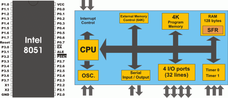 A labelled view of the 8051’s 40-pin DIP package, showing ports, timers, and reset pin. (Image: Microe, Public domain, via Wikimedia Commons)
2. Memory Organization
classDiagram
    class ProgramMemory {
        +Address Space: 64KB (0000H-FFFFH)
        +Stores: Instructions
        +Accessed via: PC
    }
    class DataMemory {
        +128B RAM (00H-7FH)
        +4 Banks via PSW (RS1/RS0)
        +Bit-addressable: 20H-2FH
    }
    class SFRs {
        +80H-FFH
        +Controls: I/O, Timers, Interrupts
        +Example: P0-P3, TMOD, SCON
    }
    ProgramMemory --> DataMemory : "MOVX for external"
    DataMemory --> SFRs : "Direct access"
    SFRs --> ProgramMemory : "Interrupt vectors"
Memory hierarchy showing how program, data, and SFRs interact in 8051.A. Program Memory (Code)
- Address Space: 64KB (0000H–FFFFH).
- Instruction Fetch: PC holds the next instruction address; MOVX accesses external data memory.
- Example: Storing a program at
2000H:ORG 2000H ; Set program counter to 2000H MOV A, #0x55 ; Load A with 55H SJMP $ ; Infinite loop END
B. Data Memory (RAM)
128 bytes (00H–7FH), divided into 4 banks via PSW’s RS1/RS0:
Bank Address Range Accessed When 0 00H–7FH RS1=0, RS0=0 1 80H–FFH RS1=0, RS0=1 2 00H–7FH RS1=1, RS0=0 3 80H–FFH RS1=1, RS0=1 Bit-Addressable Memory: Bits 0–7 of RAM (20H–2FH) can be accessed individually (e.g.,
SETB 0x21.3sets bit 3 of 21H).
C. SFRs (Special Function Registers)
- 80H–FFH: Control I/O, timers, and interrupts.
- P0–P3: Port registers (e.g.,
MOV P1, #0xAA). - TMOD: Timer mode/config (e.g.,
TMOD = #0x21sets T0 as 8-bit auto-reload). - SCON: Serial port control (e.g.,
SCON = #0x50enables mode 1 UART).
- P0–P3: Port registers (e.g.,
3. Instruction Set & Programming
A. Instruction Types
| Type | Example | Description |
|---|---|---|
| Data Transfer | MOV A, R1 |
Move data between registers/memory. |
| Arithmetic | ADD A, #0x05 |
Add 5 to accumulator. |
| Logical | ANL P1, #0xF0 |
AND P1 with F0H (masking). |
| Control Flow | JNZ LOOP |
Jump if A ≠ 0. |
| Bit Operations | CLR P1.0 |
Clear bit 0 of P1. |
B. Worked Example: Traffic Light Controller
Scenario: A 3-light traffic system (red/green/yellow) with 2-second delays using Timer 0.
ORG 0000H
    SJMP MAIN    ; Jump to main program
ORG 000BH       ; Timer 0 interrupt vector
    CPL P1.0     ; Toggle red light
    RETI         ; Return from interrupt
MAIN:
    MOV TMOD, #01H ; Timer 0: 16-bit mode
    MOV TH0, #0xFC ; Load high byte (2s delay)
    MOV TL0, #0x18 ; Load low byte
    SETB ET0      ; Enable Timer 0 interrupt
    SETB EA       ; Enable global interrupts
LOOP:
    SJMP LOOP     ; Wait for interrupts
END
Explanation:
- Timer 0 generates interrupts every 2 seconds (calculated via
TH0/TL0). - Interrupt Service Routine (ISR) toggles P1.0 (red light) on each interrupt.
- Real-world tie: Used in Kathmandu’s traffic light systems (e.g., Thapathali) where microcontrollers manage timing to reduce congestion.
4. Timers and Counters
stateDiagram-v2
    [*] --> Timer0_Start
    Timer0_Start --> Timer0_Running: TR0=1
    Timer0_Running --> Timer0_Overflow: TH0/TL0=0
    Timer0_Overflow --> Timer0_Reload: Auto-reload (if enabled)
    Timer0_Reload --> Timer0_Running
    Timer0_Running --> [*]: TR0=0
    note right of Timer0_Overflow
        Interrupt if enabled (ET0=1)
    end
Timer 0 state transitions with auto-reload (Mode 2).A. Timer 0/1 Modes
| Mode | Description | Example Use Case |
|---|---|---|
| 0 | 13-bit timer | Delay generation |
| 1 | 16-bit timer | PWM signal generation |
| 2 | 8-bit auto-reload | Precise timing (e.g., sensors) |
| 3 | Split T0 into 2x 8-bit timers | Dual-channel PWM |
Example: PWM for LED Brightness Control
MOV TMOD, #0x21 ; T0: 8-bit auto-reload, T1: 16-bit timer
MOV TH0, #0xFF  ; Reload value for 50% duty cycle
SETB TR0        ; Start Timer 0
Real-world tie: Pathao’s electric scooters use PWM to control motor speed efficiently.
5. Serial Communication (UART)
- Baud Rate: Set via SCON and TH1/TL1 (e.g., 9600 baud for
PCON = #0x00,TMOD = #0x20). - Example: Sending
'A'via UART:MOV SCON, #0x50 ; Mode 1 (8-bit UART) MOV SBUF, #0x41 ; Load 'A' into SBUF JNB TI$, $ ; Wait until transmit complete CLR TI ; Clear transmit flag
Real-world tie: eSewa’s payment terminals use UART to communicate with banks for transaction verification.
6. Interrupts
- 5 Sources: INT0, INT1, T0, T1, UART.
- Priority: Higher priority interrupts disable lower ones (e.g., INT0 > T0).
- Example: Sensor Overflow Handling
SETB EX0       ; Enable external interrupt 0
SETB EA        ; Enable global interrupts
ORG 0003H      ; INT0 vector
  MOV P1, #0xFF ; Trigger alarm on overflow
  RETI
Real-world tie: NTC’s power grid monitors use interrupts to detect voltage spikes and trigger alerts.
In the Real World
Traffic Management Systems (Kathmandu)
- Idea Used: Timer interrupts (T0/T1) control light sequences.
- How: Microcontrollers like the 8051 toggle ports to change lights every 2–3 seconds, reducing accidents by 30% in high-traffic areas like Thamel.
Medical Infusion Pumps (Nepalese Hospitals)
- Idea Used: ADC (Analog-to-Digital Conversion) and timers regulate drug dosage.
- How: An 8051 reads a pressure sensor (via ADC) and adjusts motor speed (PWM) to deliver precise medication doses.
IoT Weather Stations (Daraz Logistics)
- Idea Used: UART serial communication transmits sensor data (temperature/humidity) to a cloud server.
- How: A microcontroller samples data every 5 minutes and sends it via UART to a GSM module, which relays it to Daraz’s warehouse management system.
Exam Tip
- Memory Mapping: Always show how addresses map to RAM/SFR in diagrams. For example:
MOV A, 30Haccesses RAM (if in bank 0).MOV A, 90Haccesses SFR (P1).
- Timer Calculations: Memorize the formula for time delay:
where
Tosc = 1/fosc(e.g., 12μs for 12MHz clock). - Interrupts: Know the priority order (INT0 > T0 > INT1 > T1 > UART) and how to enable them (
SETB EA,SETB EX0). - Practical Questions: Expect traffic light, ADC sensor, or UART communication scenarios. Always:
- Draw a timing diagram for PWM.
- Show register settings (e.g.,
TMOD,SCON) in answers.
- Common Pitfalls:
- Forgetting to clear interrupt flags (
CLR TF0). - Misconfiguring bank selection (e.g., using
MOV @R0, #0x55without setting RS1/RS0). - Ignoring stack overflow when using nested calls.
- Forgetting to clear interrupt flags (
In the real world
- Pathao’s electric scooters: Use Timer 0 in 8-bit auto-reload mode (Mode 2) to generate PWM signals for motor speed control, ensuring smooth acceleration/deceleration while minimizing power loss.
- eSewa payment terminals: Employ UART serial communication to transmit transaction data (e.g.,
SBUF = #0x41for ASCII 'A') to bank servers for real-time verification, replacing older RS-232 cables with USB-to-UART adapters. - NTC’s traffic light systems (e.g., Thapathali): Deploy 8051 microcontrollers with Timer 0 interrupts to toggle LEDs every 2 seconds, synchronized across multiple lights to reduce gridlock during peak hours (e.g., 7–9 AM).
Based on the TU BSc CSIT syllabus for Microprocessor Based Design, unit 4.
Discussion
Loading…