Microprocessor Based DesignUnit 212 min read
Sensors & Actuators: Types, Working, and Applications
Unit 2 of Microprocessor Based Design explores how sensors detect physical quantities (light, temperature, motion) and actuators convert electronic signals into mechanical motion or control, with real-world examples from Nepalese tech (eSewa, Pathao) and hands-on programming traces for 8051 microcontrollers.
TAKEAWAYS:
- Sensors convert physical signals (e.g., temperature, pressure) into electrical signals for processing, while actuators perform physical actions (e.g., opening a valve, moving a motor) based on commands.
- Analog sensors (e.g., thermistors, LDRs) output continuous signals, while digital sensors (e.g., encoders, ultrasonic sensors) provide discrete data.
- Actuators include linear (solenoids), rotary (servo motors), and non-mechanical types (LEDs, relays), each suited for specific tasks like automation or feedback control.
- Noise and calibration are critical: sensors require filtering (e.g., RC circuits) and periodic adjustments to ensure accuracy in real-world applications.
- The 8051 microcontroller interfaces with sensors/actuators via ports (P0–P3), ADC (for analog sensors), and timers (for pulse-width modulation to control actuators).
- Real-world tie: Pathao’s ride-matching uses GPS sensors (actuators adjust driver routes) and ultrasonic sensors in self-driving prototypes.
1. Sensors: The Eyes and Ears of Embedded Systems
Sensors are devices that detect physical phenomena (e.g., light, heat, motion) and convert them into electrical signals for a microcontroller to process. They are the input side of any embedded system, enabling it to interact with the real world.
1.1 Classification of Sensors
Sensors are categorized based on:
- Physical Quantity Measured: Temperature, light, pressure, proximity, etc.
- Output Type: Analog or digital.
- Working Principle: Passive (require external power) or active (generate their own signal).
mindmap
  root((Sensors))
    Analog
      Thermistor["Temperature (Resistance-based)"]
      LDR["Light (Resistance-based)"]
      Potentiometer["Position (Variable resistor)"]
    Digital
      Encoder["Rotary position (Pulses)"]
      Ultrasonic["Distance (Sound waves)"]
      IR["Proximity (Infrared)"]
    Specialized
      Accelerometer["Motion (MEMS)"]
      Gyroscope["Angular velocity (MEMS)"]
      Hall-Effect["Magnetic field (Semiconductor)"]
1.2 Key Sensor Types and Their Workings
| Sensor | Measured Quantity | Working Principle | Example Applications |
|---|---|---|---|
| Thermistor | Temperature | Resistance changes with temperature | Oven temperature control, weather stations |
| LDR (Light Dependent Resistor) | Light Intensity | Resistance decreases with light exposure | Streetlight automation, camera light meters |
| Ultrasonic Sensor | Distance | Echo time of sound waves | Parking sensors, robot obstacle avoidance |
| IR Sensor | Proximity/Object | Infrared reflection detection | Touchless taps, security alarms |
| Potentiometer | Position/Angle | Variable resistance based on shaft rotation | Volume knobs, robot arm positioning |
| Accelerometer | Acceleration | MEMS-based capacitance change | Smartphone orientation, fitness trackers |
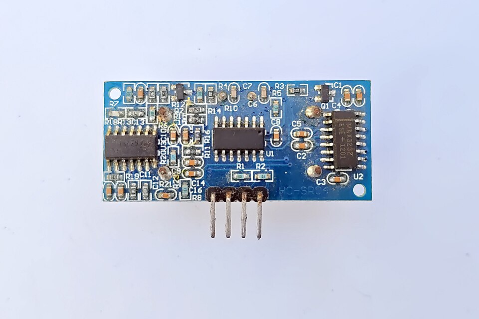 HC-SR04 ultrasonic sensor with trigger/echo pins for distance measurement (Image: Suyash Dwivedi, CC BY-SA 4.0, via Wikimedia Commons)
1.3 Analog vs. Digital Sensors
| Feature | Analog Sensors | Digital Sensors |
|---|---|---|
| Output | Continuous voltage/current | Discrete pulses or binary data |
| Processing | Requires ADC (Analog-to-Digital Converter) | Directly readable by microcontroller |
| Accuracy | High resolution but prone to noise | Less resolution but immune to noise |
| Examples | Thermistor, LDR, strain gauge | Encoder, ultrasonic, digital temperature ICs |
Worked Example: Interfacing an LDR with 8051 An LDR’s resistance changes with light. To read it:
- Connect the LDR in a voltage divider with a fixed resistor (e.g., 10kΩ).
- The midpoint voltage is fed to an ADC (e.g., ADC0808).
- The 8051 reads and maps it to light intensity using: Where (8051’s ).
- Real-world tie: eSewa’s automated teller machines (ATMs) use ambient light sensors (LDRs) to adjust screen brightness for better visibility.
2. Actuators: Turning Data into Action
Actuators are the output devices that convert electrical signals from a microcontroller into physical actions. They enable embedded systems to control the real world.
2.1 Types of Actuators
Actuators are classified based on motion and energy conversion:
mindmap
  root((Actuators))
    Linear
      Solenoid["Electromagnetic (Push/Pull)"]
      Piezoelectric["Vibration (High-frequency)"]
    Rotary
      DC Motor["Speed control via PWM"]
      Stepper Motor["Precise angular steps"]
      Servo Motor["Position control (0–180°)"]
    Non-Mechanical
      LED["Light output"]
      Relay["Electrical switch"]
      LCD["Display output"]
2.2 Key Actuator Types and Applications
| Actuator | Function | Working Principle | Example Applications |
|---|---|---|---|
| DC Motor | Rotary motion | Magnetic field interaction with current | Fan control, robot wheels |
| Servo Motor | Precise angular positioning | PWM signal controls horn position | Robot arms, drone stabilizers |
| Solenoid | Linear motion | Electromagnetic coil pulls/plunger | Door locks, valve control |
| Stepper Motor | Step-by-step rotation | Discrete electrical pulses move rotor | 3D printer axes, CNC machines |
| Relay | Electrical switching | Electromagnet closes/contacts | High-voltage control (e.g., NTC substations) |
| LED | Light output | Current through semiconductor emits light | Indicators, traffic lights |
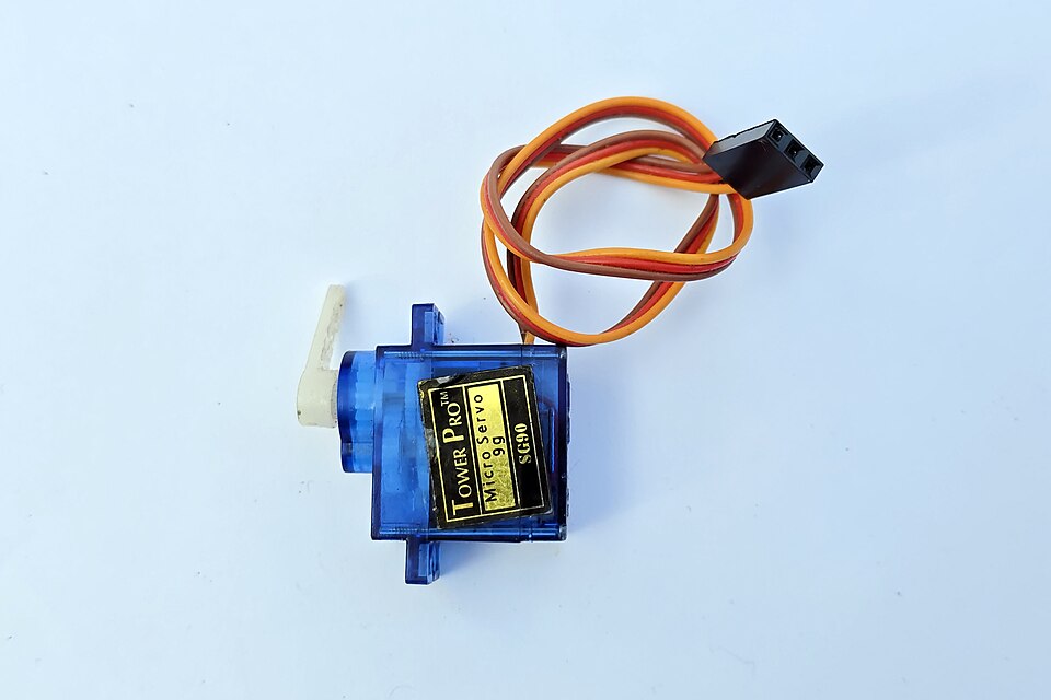 Servo motor with control wires (power, ground, signal) for angle positioning (Image: Suyash Dwivedi, CC BY-SA 4.0, via Wikimedia Commons)
2.3 Controlling Actuators with 8051
Actuators require precise control signals:
- DC/Servo Motors: Use PWM (Pulse Width Modulation) via Timer 1 of 8051.
// 8051 PWM for DC Motor (50% duty cycle) void setup_pwm() { TMOD = 0x11; // Timer 1 in Mode 1 (8-bit auto-reload) TH1 = 0xFD; // Reload value for ~1ms timer TL1 = 0xFD; ET1 = 1; // Enable Timer 1 interrupt TR1 = 1; // Start Timer 1 } - Stepper Motors: Use H-bridge drivers (e.g., L298N) with sequential pulses.
- Relays: Controlled via GPIO pins (e.g.,
P1.0 = 1to activate).
Worked Example: Traffic Light Control with 8051 A traffic light system uses:
- Inputs: Infrared sensors to detect vehicles.
- Outputs: Red/Yellow/Green LEDs (actuators) controlled via PWM.
- Logic:
- If
IR_sensor = 1(vehicle detected), turn Green LED on for 30s. - After 30s, switch to Yellow for 5s, then Red.
- If
- 8051 Code Snippet:
Real-world tie: Kathmandu’s smart traffic lights use similar logic with inductive loop sensors (inputs) and high-power relays (actuators) to manage traffic flow dynamically.void traffic_light() { while(1) { if (IR_sensor_status) { P1 = 0x02; // Green LED on (P1.1) delay(30000); // 30s P1 = 0x04; // Yellow LED on (P1.2) delay(5000); // 5s P1 = 0x08; // Red LED on (P1.3) } } }
3. Sensor-Actuator Interfaces with 8051
The 8051 microcontroller interfaces with sensors/actuators via:
- Ports (P0–P3): For digital signals (e.g., buttons, LEDs).
- ADC (Analog-to-Digital Converter): For analog sensors (e.g., thermistor).
- Timers/Counters: For PWM (actuators) or pulse counting (e.g., ultrasonic sensors).
3.1 ADC for Analog Sensors
The 8051 lacks a built-in ADC, so an external ADC (e.g., ADC0808) is used:
- Steps:
- Start conversion by setting
ALE = 1andSTART = 1. - Read 8-bit digital value from
P0. - Convert to physical quantity (e.g., temperature in °C).
- Start conversion by setting
Worked Example: Temperature Monitoring with LM35 The LM35 outputs . To read temperature:
- Connect LM35 to ADC0808.
- 8051 reads ADC value .
- Temperature °C (since ).
3.2 Noise and Calibration
- Noise: Unwanted signals (e.g., electromagnetic interference) distort sensor readings.
- Solutions:
- Hardware: Use capacitors (e.g., 0.1µF) to filter noise.
- Software: Apply moving averages or median filters.
- Solutions:
- Calibration: Adjusting sensor output to match real-world values.
- Example: A thermistor may read 1000Ω at 25°C; calibration maps this to the correct temperature.
4. Real-World Applications in Nepal
4.1 eSewa: Biometric Authentication
- Sensors Used:
- Fingerprint scanner (digital sensor for biometric data).
- IR proximity sensor (detects finger placement).
- Actuators:
- Buzzer (confirms successful authentication).
- LED indicators (shows processing status).
4.2 Pathao: Ride-Matching and Safety
- Sensors:
- GPS module (tracks driver/ride location).
- Accelerometer (detects sudden braking for safety alerts).
- Actuators:
- Servo motors (adjust camera tilt in driver cabs).
- Haptic feedback (vibrates phone for ride updates).
4.3 NTC’s Smart Grid Monitoring
- Sensors:
- Current/voltage sensors (monitor power usage).
- Temperature sensors (prevent overheating in transformers).
- Actuators:
- Relays (automatically reroute power during outages).
- LED displays (show grid status to technicians).
5. Common Mistakes and Troubleshooting
| Issue | Cause | Solution |
|---|---|---|
| Sensor reading fluctuates wildly | Noise or loose connections | Add capacitors, check wiring |
| Actuator doesn’t respond | Incorrect PWM signal or power issue | Verify timer settings, check power supply |
| ADC readings are inconsistent | Wrong reference voltage or timing | Use stable , delay after start |
| Stepper motor misses steps | Insufficient current or wrong sequence | Use driver IC (e.g., ULN2003), check pulse order |
## In the Real World
Khalti’s Payment Terminals
- Sensors: Magnetic stripe readers (analog/digital) detect card swipes.
- Actuators: Relays switch high-voltage circuits to process payments securely.
Daraz’s Warehouse Automation
- Sensors: RFID tags (digital) track inventory movement.
- Actuators: Conveyor belts (DC motors) sort packages based on sensor data.
Ncell’s Base Station Cooling
- Sensors: Thermistors monitor temperature inside server racks.
- Actuators: Fans (DC motors) adjust speed via PWM from the control system.
## Exam Tip
- Diagrams are mandatory: Always draw:
- Sensor/actuator connection diagrams (e.g., LDR with voltage divider).
- 8051 pinout for interfacing (e.g., ADC0808 with P0–P2).
- Code snippets: Expect questions on:
- ADC initialization and reading.
- PWM generation for motors.
- Applications: Relate sensors/actuators to Nepali tech (e.g., "How would you design a smart irrigation system for terai farms?").
- Common pitfalls:
- Forgetting to enable ADC’s
CS(chip select) orEOC(end-of-conversion) flags. - Misconfiguring timer modes for PWM (e.g., using Mode 0 instead of Mode 1).
- Forgetting to enable ADC’s
- Numerical problems: Practice converting ADC values to physical quantities (e.g., "An LDR reads 128 on a 0–255 scale with . Calculate light intensity if dark = 0Ω, bright = 10kΩ.").
Based on the TU BSc CSIT syllabus for Microprocessor Based Design, unit 2.
Discussion
Loading…