Advanced Networking with IPv6Unit 120 min read
Networking Basics: Models, Protocols & Topologies
Unit 1 of Advanced Networking with IPv6 covers foundational networking concepts including the OSI and TCP/IP layered models, protocol functions, network topologies, and real-world communication examples to build intuition for how data travels across networks.
TAKEAWAYS:
- Understand the 7-layer OSI model and 4-layer TCP/IP model and how they abstract networking functions into logical layers.
- Learn how protocols (like HTTP, FTP, DNS) operate at different layers to enable communication between devices.
- Compare network topologies (bus, star, mesh, ring) and analyze their advantages/disadvantages in real-world deployments.
- Trace how data encapsulation (headers, trailers) transforms data from application layer to physical transmission.
- Apply networking principles to analyze everyday systems like eSewa transactions or Ncell call routing.
- Recognize how physical media (fiber, copper, wireless) and logical addressing (IPv4/IPv6) enable global connectivity.
1. Why Networking? The Big Picture
Networking connects devices to share resources, communicate, and collaborate. From a single computer to the entire internet, networks enable:
- Resource sharing (printers, files, databases)
- Communication (email, video calls, messaging)
- Distributed computing (cloud services, blockchain)
1.1 The Need for Standardization
Without standards, devices from different manufacturers cannot communicate. Standards define:
- How data is formatted (packets, frames)
- How devices address each other (IP addresses, MAC addresses)
- How errors are detected/corrected (checksums, retries)
Example: If your laptop (Windows) and a friend’s phone (Android) couldn’t agree on how to send messages, WhatsApp wouldn’t work.
2. The OSI Model: A Blueprint for Networking
The Open Systems Interconnection (OSI) model is a 7-layer framework that standardizes how networks function. Each layer has a specific role, and layers only communicate with adjacent layers.
2.1 Layer-by-Layer Breakdown
| Layer | Name | Function | Protocols/Examples | Data Unit |
|---|---|---|---|---|
| 7 | Application | Provides network services to end-users (e.g., email, file transfer). | HTTP, FTP, SMTP, DNS | Data |
| 6 | Presentation | Translates, encrypts, or compresses data. | SSL/TLS, JPEG, MPEG | Data |
| 5 | Session | Manages sessions between applications (e.g., opening/closing connections). | NetBIOS, RPC | Data |
| 4 | Transport | Ensures end-to-end communication (reliable/unreliable delivery). | TCP (reliable), UDP (fast) | Segments |
| 3 | Network | Handles routing and logical addressing (IP addresses). | IP, ICMP, IPv6 | Packets |
| 2 | Data Link | Manages node-to-node communication (MAC addresses, error detection). | Ethernet, Wi-Fi, PPP | Frames |
| 1 | Physical | Transmits raw bits over physical media (cables, wireless signals). | USB, Ethernet, Fiber Optic | Bits |
Key Idea: Each layer adds headers/trailers (encapsulation) and passes data down. At the destination, layers strip headers (decapsulation).
2.2 Worked Example: Sending an Email (HTTP Request)
Let’s trace how an email request travels from your laptop to a server:
Application Layer (Layer 7):
- You type an email in Gmail (HTTP protocol).
- Data =
"Subject: Hello\nBody: How are you?"
Presentation Layer (Layer 6):
- Data is compressed/encrypted (if HTTPS is used).
- Data =
Encrypted("Subject: Hello...")
Session Layer (Layer 5):
- A session is established between your browser and Gmail’s server.
- Data remains the same (session management is invisible).
Transport Layer (Layer 4 - TCP):
- Data is split into segments and assigned a sequence number for reliability.
- Segment =
SEQ=1000 | ACK=0 | Data=Encrypted("Subject:...")
Network Layer (Layer 3 - IPv4/IPv6):
- Segments are packed into packets with source/destination IP addresses.
- Packet =
Source IP: 192.168.1.2 | Dest IP: 142.250.190.46 | Segment Data
Data Link Layer (Layer 2 - Ethernet):
- Packets are framed with MAC addresses (local network).
- Frame =
Dest MAC: AA:BB:CC:DD:EE:FF | Source MAC: 00:11:22:33:44:55 | Packet Data
Physical Layer (Layer 1):
- Frames are converted to bits (0s and 1s) and sent over Ethernet cable/wireless.
- Bits =
10101010...(binary representation of the frame).
At the Server:
- The process reverses: bits → frames → packets → segments → data.
- Gmail’s server decrypts/compresses and delivers the email.
3. The TCP/IP Model: A Simplified 4-Layer Approach
While OSI is theoretical, TCP/IP (used in the internet) simplifies networking into 4 layers:
| TCP/IP Layer | OSI Equivalent | Key Functions |
|---|---|---|
| Application | Layers 5-7 | HTTP, FTP, DNS, SMTP |
| Transport | Layer 4 | TCP (reliable), UDP (fast) |
| Internet | Layer 3 | IP (routing), ICMP (error messages) |
| Network Access | Layers 1-2 | Ethernet, Wi-Fi, PPP |
Why TCP/IP?
- Simpler (only 4 layers).
- Used in real-world networks (internet, LANs).
- More practical for implementation.
4. Network Topologies: How Devices Are Connected
Topology refers to how devices are physically or logically connected. Each has trade-offs in cost, scalability, and reliability.
4.1 Common Topologies
| Topology | Description | Advantages | Disadvantages | Real-World Example |
|---|---|---|---|---|
| Bus | All devices share a single communication line. | Simple, cheap to install. | Single point of failure; slow for many devices. | Old Ethernet (10BASE2). |
| Star | All devices connect to a central hub/switch. | Easy to manage; adding/removing devices is simple. | Central hub is a single point of failure. | Home Wi-Fi networks, office LANs. |
| Ring | Devices are connected in a closed loop; data travels in one direction. | Predictable data flow; no collisions. | If one device fails, the whole network fails. | Token Ring networks (rare today). |
| Mesh | Every device is connected to every other device (full mesh) or some others (partial mesh). | Highly reliable; no single point of failure. | Expensive; complex to manage. | Military networks, some IoT setups. |
| Hybrid | Combines two or more topologies (e.g., star + bus). | Balances cost and reliability. | Complex design. | Corporate networks (star backbone + bus segments). |
4.2 Worked Example: Ncell’s Mobile Network Topology
Ncell’s 4G/5G network uses a hybrid topology:
- Star Topology (Core Network):
- Your phone connects to a local cell tower (base station) in a star pattern.
- Mesh Topology (Backhaul):
- Cell towers are connected via fiber optic cables in a partial mesh for redundancy.
- Hierarchical Routing:
- Data from your phone → local tower → regional gateway → Ncell’s core network → internet.
Why?
- Star ensures your phone has a direct link to the tower.
- Mesh backhaul prevents outages if one fiber cable fails.
5. Data Encapsulation and Decapsulation
Data moves down the layers (encapsulation) and up the layers (decapsulation) with headers/trailers added at each step.
sequenceDiagram
    participant App as Application Layer
    participant Pres as Presentation Layer
    participant Trans as Transport Layer
    participant Net as Network Layer
    participant DLink as Data Link Layer
    participant Phys as Physical Layer

    App->>Pres: Data (e.g., "Hello")
    Pres->>Trans: Data + Encryption Header
    Trans->>Net: Segment + TCP Header (Ports, Seq#)
    Net->>DLink: Packet + IP Header (Source/Dest IP)
    DLink->>Phys: Frame + MAC Header (Source/Dest MAC)
    Phys-->>Phys: Bits (0s and 1s) over cable/wireless
    Phys->>DLink: Frame (received)
    DLink->>Net: Packet (strips MAC header)
    Net->>Trans: Segment (strips IP header)
    Trans->>Pres: Data (strips TCP header)
    Pres->>App: Decrypted Data ("Hello")
Key Fields in Headers:
| Layer | Header Fields |
|---|---|
| Transport (TCP) | Source Port, Destination Port, Sequence Number, Acknowledgment Number, Checksum |
| Network (IP) | Source IP, Destination IP, Version (4/6), TTL (Time to Live), Protocol (TCP/UDP) |
| Data Link (Ethernet) | Destination MAC, Source MAC, EtherType, CRC (error checking) |
6. Physical Media: How Data Travels
Data is transmitted over physical media, each with speed, distance, and cost trade-offs.
| Medium | Type | Speed | Max Distance | Use Case | Example |
|---|---|---|---|---|---|
| Twisted Pair | Copper | 10 Mbps–10 Gbps | 100m (Cat5e) | Ethernet in offices/homes. | Cat6 cable for LAN. |
| Coaxial | Copper | 10 Mbps–1 Gbps | 500m | Cable TV, older Ethernet (10BASE5). | RG-6 cable for TV. |
| Fiber Optic | Glass/Fiber | 10 Mbps–100 Tbps | 100+ km | Backbone networks, ISPs. | NTC’s fiber backbone. |
| Wireless | Radio/Wi-Fi | 1–6 Gbps | 100m (Wi-Fi 6) | Home networks, mobile data. | Ncell 4G/5G towers. |
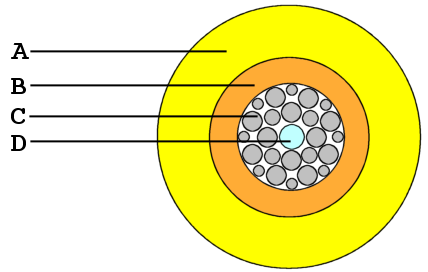 A labeled diagram showing the glass core, cladding, and protective layers. (Image: J.P.Lon at English Wikipedia, CC BY 2.5, via Openverse)
6.1 Worked Example: eSewa Payment Over the Internet
When you pay a bill via eSewa:
- Your phone sends data over Wi-Fi (wireless medium) to your router.
- Router forwards it via fiber optic cable to NTC’s ISP.
- ISP routes it through undersea fiber cables (if international) or terrestrial fiber (if domestic).
- eSewa’s server receives the request via data centers connected by high-speed fiber.
Why Fiber?
- Speed: Fiber supports 100+ Gbps, handling thousands of transactions per second.
- Reliability: Immune to electromagnetic interference (unlike copper).
- Security: Harder to tap into than wireless signals.
7. Logical vs. Physical Addressing
| Address Type | Layer | Example | Purpose |
|---|---|---|---|
| Physical (MAC) | Data Link (L2) | 00:1A:2B:3C:4D:5E |
Identifies a network interface card (NIC) on a local network. |
| Logical (IP) | Network (L3) | 192.168.1.1 or 2001:db8::1 |
Identifies a device on the internet (global uniqueness). |
How They Work Together:
- Your laptop wants to send data to Google’s server (IP: 142.250.190.46).
- Your laptop knows Google’s IP address (logical) but not its MAC address (physical).
- It sends an ARP request (on the local network) to find Google’s MAC address.
- ARP = Address Resolution Protocol (maps IP → MAC).
- Once it gets the MAC, it frames the data and sends it.
8. Protocols: Rules for Communication
A protocol is a set of rules governing how devices communicate. Examples:
- HTTP/HTTPS: Web browsing (Layer 7).
- TCP/UDP: Reliable/fast transport (Layer 4).
- IP (IPv4/IPv6): Routing (Layer 3).
- Ethernet: Local network framing (Layer 2).
8.1 TCP vs. UDP: A Comparison
| Feature | TCP (Transmission Control Protocol) | UDP (User Datagram Protocol) |
|---|---|---|
| Reliability | Reliable (acknowledgments, retries). | Unreliable (no guarantees). |
| Connection | Connection-oriented (handshake before data). | Connectionless (sends data immediately). |
| Speed | Slower (due to acknowledgments). | Faster (no overhead). |
| Use Cases | Web browsing (HTTP), email (SMTP), file transfer (FTP). | Video streaming (YouTube), VoIP (Zoom), DNS. |
| Header Size | 20 bytes (larger). | 8 bytes (smaller). |
Worked Example: WhatsApp Calls (UDP vs. TCP)
- WhatsApp calls use UDP because:
- Low latency is critical for real-time voice.
- A few lost packets (due to UDP’s unreliability) are less noticeable than delayed packets.
- WhatsApp messages use TCP because:
- Reliability matters (you want every message delivered).
9. Network Devices: Extending Connectivity
Devices connect, route, and manage networks:
| Device | Layer | Function | Example |
|---|---|---|---|
| Hub | Physical (L1) | Broadcasts all data to every port (no intelligence). | Old Ethernet hubs. |
| Switch | Data Link (L2) | Forwards frames only to the intended port (uses MAC tables). | Home/office switches. |
| Router | Network (L3) | Routes packets between networks using IP addresses. | ISP routers, NTC’s backbone. |
| Bridge | Data Link (L2) | Connects two LANs (filters traffic between them). | Rare in modern networks. |
| Gateway | Multiple Layers | Connects dissimilar networks (e.g., LAN to internet). | Home modem/router. |
| Repeater | Physical (L1) | Regenerates signals to extend distance (no intelligence). | Old Ethernet repeaters. |
9.1 Worked Example: Daraz Order Delivery (Routing)
When you order from Daraz:
- Your phone (192.168.1.5) sends a request to Daraz’s server (IP: 13.229.178.246).
- The request travels:
- Your home router (192.168.1.1) → ISP (NTC) → Daraz’s data center (AWS servers in US/EU).
- Routers at each step:
- Check the destination IP (13.229.178.246).
- Use routing tables to decide the next hop (e.g., "send to ISP’s gateway").
- DNS resolves
daraz.com.np→13.229.178.246before the request is sent.
Why Routers Matter:
- Without routers, your request would only stay in your local network.
- Routers connect networks (LAN → ISP → Internet → Daraz).
In the Real World
eSewa Payments (IPv4/IPv6 + TCP)
- When you pay a bill, eSewa’s servers use TCP (Layer 4) for reliable transactions.
- Your phone connects via Wi-Fi (IEEE 802.11 standard, Layer 2) to your router.
- The payment data travels over NTC’s fiber backbone (Physical Layer) to eSewa’s data center.
- IPv4/IPv6 (Layer 3) ensures your request reaches the correct server globally.
Pathao Ride Booking (UDP + DNS)
- When you book a ride, Pathao’s app uses UDP (Layer 4) for fast location updates (your GPS data).
- DNS (Application Layer) resolves
pathao.comto its server IP. - The driver’s app communicates with Pathao’s servers via TCP (for ride details) and UDP (for real-time location tracking).
Ncell 4G/5G Network (Star + Mesh Topology)
- Your phone connects to a cell tower (star topology).
- Towers are linked via fiber optic cables (partial mesh) for redundancy.
- IPv6 (Layer 3) is used to handle the massive number of IoT devices (e.g., smart meters, drones).
- QoS (Quality of Service) ensures voice calls (low latency) work better than video streaming.
Exam Tip
What to Expect in the Exam
Layer Identification:
- Questions will ask: "Which OSI layer does HTTP operate at?" → Answer: Application (Layer 7).
- Tip: Memorize the mnemonic for OSI layers: "All People Seem To Need Data Processing" (Application, Presentation, Session, Transport, Network, Data Link, Physical).
Protocol Matching:
- "Which protocol provides reliable delivery?" → TCP.
- "Which protocol is used for email?" → SMTP (Application Layer).
Topology Analysis:
- "Why is a star topology preferred in offices?" → Easy to manage, single cable failure doesn’t crash the whole network.
- Draw a diagram if asked to compare topologies.
Data Encapsulation:
- "Show the encapsulation process for an HTTP request." → Draw the layers and label headers at each step.
- Common mistake: Forgetting MAC addresses (Layer 2) in local networks.
Real-World Scenarios:
- "Explain how a bank’s online transaction works using networking layers." → Cover TCP (reliability), IP (routing), and physical media (fiber).
- Tip: Relate to eSewa, Daraz, or Ncell for local relevance.
Short Answer Questions:
- Define protocol, MAC address, router, encapsulation.
- Example:
- "What is the difference between a switch and a hub?"
- Switch: Forwardes frames to the correct port (Layer 2).
- Hub: Broadcasts to all ports (Layer 1).
- "What is the difference between a switch and a hub?"
How to Score Full Marks
- Draw diagrams for topologies, encapsulation, or protocol exchanges.
- Use real-world examples (eSewa, Ncell, Daraz) to explain concepts.
- Label all parts of headers (e.g., TCP segment fields, IP packet fields).
- Compare and contrast (e.g., TCP vs. UDP, OSI vs. TCP/IP).
- Explain trade-offs (e.g., why fiber is better than copper for long distances).
Common Pitfalls to Avoid
- Mixing OSI and TCP/IP layers (e.g., saying HTTP is Layer 5).
- Forgetting MAC addresses in local network questions.
- Assuming all protocols are reliable (UDP is not!).
- Ignoring physical media (exams may ask about fiber vs. copper).
- Not showing all layers in encapsulation questions (start from Application down to Physical).
Final Thought: Networking is everywhere—from your WhatsApp call to Nepal’s stock market (NEPSE). Mastering the OSI model, protocols, and topologies will help you design, troubleshoot, and optimize real-world networks. Practice drawing diagrams and relating concepts to daily tech use (eSewa, Daraz, Ncell) to ace your exam!
Based on the TU BSc CSIT syllabus for Advanced Networking with IPv6, unit 1.
Discussion
Loading…