Computer and Information TechnologyUnit 511 min read
Computer Networks and Communication – Key Concepts
Unit 5 of Computer and Information Technology: provides a comprehensive understanding of computer networking fundamentals, including network types, topologies, layered models, packet structure, addressing, routing, key protocols, and real‑world applications.
Key points
- Networks enable resource sharing and communication across devices.
- The OSI and TCP/IP models structure network functions into layers.
- Packet headers carry addressing, control, and error‑checking information.
- Routing, switching, and protocols determine how data traverses networks.
- Security mechanisms such as TLS/SSL, VPN, and firewalls protect data.
Overview
Computer networks are collections of interconnected devices that exchange data. They form the backbone of modern information systems, enabling services such as e‑commerce, online banking, and real‑time communication. Unit 5 covers the essential building blocks that make networking possible: the types of networks, physical and logical topologies, layered communication models, packet formats, addressing schemes, routing and switching, key protocols, and security considerations.
1. Types of Computer Networks
| Size | Typical Use | Example | Key Characteristics |
|---|---|---|---|
| PAN (Personal Area Network) | Devices within a person’s reach | Bluetooth headset ↔ smartphone | < 10 m, low power |
| LAN (Local Area Network) | Single building or campus | Campus Wi‑Fi | < 10 km, high bandwidth |
| MAN (Metropolitan Area Network) | City‑wide | City Wi‑Fi, fiber backbones | 10–50 km, moderate bandwidth |
| WAN (Wide Area Network) | Across countries | Internet, corporate WAN | > 100 km, global reach |
Real‑world example – eSewa uses a LAN for its internal transaction processing and a WAN (Internet) to connect to banks and payment gateways.
2. Physical and Logical Topologies
| Topology | Physical Layout | Advantages | Disadvantages |
|---|---|---|---|
| Bus | All devices share a single cable | Simple, inexpensive | Single point of failure |
| Star | Devices connect to a central hub | Easy to add/remove nodes | Hub failure collapses network |
| Ring | Devices connected in a closed loop | Predictable bandwidth | Failure breaks the ring |
| Mesh | Multiple redundant paths | High reliability | Complex, costly |
| Hybrid | Combination of above | Flexibility | Complexity depends on design |
Worked example – Star topology in a university
A 100‑node campus Wi‑Fi network uses a star topology with a central switch. If a client fails, only that client is affected; the rest of the network remains operational.
3. Layered Communication Models
3.1 OSI Model
The OSI model divides network functions into seven layers:
- Physical – electrical signals, cables.
- Data Link – MAC addresses, framing, error detection.
- Network – logical addressing (IP), routing.
- Transport – reliable delivery (TCP), best‑effort (UDP).
- Session – connection management.
- Presentation – data formatting, encryption.
- Application – end‑user services (HTTP, FTP).
3.2 TCP/IP Model
The Internet protocol suite collapses OSI into four layers:
- Link – equivalent to OSI Physical + Data Link.
- Internet – IP routing.
- Transport – TCP/UDP.
- Application – HTTP, SMTP, etc.
Comparison Table
| Feature | OSI | TCP/IP |
|---|---|---|
| Number of layers | 7 | 4 |
| Standardization | ISO | IETF |
| Practical use | Reference model | Real protocols |
| Complexity | High | Lower |
4. Packet Structure
4.1 IP Packet Header
| Field | Size | Description |
|---|---|---|
| Version | 4 bits | IPv4 = 4 |
| IHL | 4 bits | Header length |
| Type of Service | 8 bits | QoS |
| Total Length | 16 bits | Header + data |
| Identification | 16 bits | Fragment ID |
| Flags | 3 bits | Fragmentation control |
| Fragment Offset | 13 bits | Fragment position |
| TTL | 8 bits | Time‑to‑live |
| Protocol | 8 bits | Upper‑layer protocol |
| Header Checksum | 16 bits | Error detection |
| Source IP | 32 bits | Sender |
| Destination IP | 32 bits | Receiver |
| Options | variable | Optional fields |
Worked example – IP header calculation
A packet from 192.168.1.10 to 10.0.0.5 has a total length of 1500 bytes.
- IHL = 5 (5 × 32 bits = 160 bits = 20 bytes).
- TTL is set to 64.
- Protocol = 6 (TCP).
The header checksum is computed over the header; if the result is 0x1A2B, the packet is transmitted.
4.2 TCP Segment Header
| Field | Size | Description |
|---|---|---|
| Source Port | 16 bits | Application port |
| Destination Port | 16 bits | Application port |
| Sequence Number | 32 bits | Data ordering |
| Acknowledgment Number | 32 bits | ACK value |
| Data Offset | 4 bits | Header length |
| Reserved | 3 bits | |
| Flags | 9 bits | SYN, ACK, FIN, etc. |
| Window | 16 bits | Flow control |
| Checksum | 16 bits | Error detection |
| Urgent Pointer | 16 bits | Urgent data |
5. Addressing and Routing
5.1 MAC Addressing
- 48‑bit hardware address (e.g., 00:1A:2B:3C:4D:5E).
- Unique per network interface.
5.2 IP Addressing
- IPv4 – 32 bits, dotted decimal.
- IPv6 – 128 bits, hexadecimal.
5.3 ARP (Address Resolution Protocol)
sequenceDiagram
    participant HostA
    participant Switch
    participant HostB
    HostA->>Switch: ARP Request (Who has 10.0.0.5?)
    Switch->>HostB: Broadcast ARP Request
    HostB->>Switch: ARP Reply (10.0.0.5 -> 00:1A:2B:3C:4D:5E)
    Switch->>HostA: ARP Reply
5.4 DHCP (Dynamic Host Configuration Protocol)
sequenceDiagram
    participant Host
    participant DHCP Server
    Host->>DHCP Server: DHCP Discover
    DHCP Server->>Host: DHCP Offer (IP, subnet, gateway)
    Host->>DHCP Server: DHCP Request
    DHCP Server->>Host: DHCP ACK
5.5 Routing Algorithms
| Algorithm | Type | Example | Complexity |
|---|---|---|---|
| Distance Vector | Iterative | RIP | O(n²) |
| Link State | Flooding | OSPF | O(n log n) |
| Path Vector | Policy based | BGP | O(n) |
6. Switching and Routing Devices
| Device | Layer(s) | Function | Example |
|---|---|---|---|
| Hub | Physical | Broadcast | Legacy LAN |
| Switch | Data Link | MAC learning | Campus switch |
| Router | Network | IP routing | ISP edge router |
| Access Point | Physical/Data Link | Wireless access | Ncell LTE base station |
| Firewall | Network/Transport | Packet filtering | Corporate perimeter |
7. Key Protocols
| Protocol | Layer | Purpose | Example |
|---|---|---|---|
| TCP | Transport | Reliable, ordered delivery | Web browsing |
| UDP | Transport | Low‑latency, no ACK | VoIP |
| IP | Network | Logical addressing | Internet |
| ICMP | Network | Error reporting | Ping |
| HTTP/HTTPS | Application | Web content | |
| SMTP | Application | Gmail | |
| DNS | Application | Name resolution | www.nepse.com |
| TLS/SSL | Presentation | Encryption | eSewa transactions |
7.1 TCP Three‑Way Handshake
sequenceDiagram
    participant Client
    participant Server
    Client->>Server: SYN (seq=100)
    Server->>Client: SYN‑ACK (seq=200, ack=101)
    Client->>Server: ACK (ack=201)
Worked example – Handshake trace
- Client sends SYN with sequence number 100.
- Server replies with SYN‑ACK, sequence 200, acknowledging 101.
- Client acknowledges with ACK, sequence 101, ack 201.
Connection established; data transfer begins.
8. Wireless Networking
- Wi‑Fi (IEEE 802.11) – 2.4 GHz, 5 GHz bands.
- LTE/5G – cellular, high throughput.
- Bluetooth – short‑range, low power.
Real‑world example – Ncell LTE
Ncell’s 4G network uses LTE architecture: eNodeB (base station) ↔ UE (mobile). LTE employs OFDMA for downlink and SC‑FDMA for uplink, providing high spectral efficiency.
9. Network Security
| Mechanism | Layer | Function | Example |
|---|---|---|---|
| Encryption | Presentation | Data confidentiality | TLS in eSewa |
| Authentication | Application | Verify identity | OAuth in Pathao |
| Firewalls | Network/Transport | Packet filtering | Corporate firewall |
| VPN | Network | Secure tunnels | Remote office access |
| IDS/IPS | Network | Intrusion detection | NetFlow analysis |
10. Quality of Service (QoS)
- Traffic shaping – bandwidth limits.
- Prioritization – voice over IP gets higher priority.
- Congestion control – TCP’s slow‑start, congestion avoidance.
Real‑world example – YouTube streaming
YouTube uses adaptive bitrate streaming (ABR). The client requests video segments at varying bitrates based on current network throughput, ensuring smooth playback.
11. Network Management
- SNMP – Simple Network Management Protocol.
- NetFlow – traffic flow monitoring.
- Syslog – event logging.
12. Emerging Trends
- Software‑Defined Networking (SDN) – decouples control plane from data plane.
- Network Function Virtualization (NFV) – virtualizes network services.
- Edge Computing – processing near data source.
13. In the real world
- eSewa – Uses TLS/SSL (Presentation layer) to encrypt online payments. The TLS handshake occurs over TCP (Transport) and IP (Network).
- Pathao – Relies on GPS‑based routing (Application) and LTE (Wireless) to dispatch drivers. The GPS data is transmitted via UDP for low latency.
- Ncell – Deploys LTE base stations (Access Point) that use OFDMA and SC‑FDMA. The eNodeB communicates with the core network over IP/MPLS (Network).
Worked real‑world example – Daraz order queue
A Daraz order placed by a customer triggers a series of messages:
- HTTP POST (Application) to Daraz server.
- TCP handshake establishes connection.
- DNS resolves Daraz domain to IP.
- TLS encrypts the payload.
- Order data is queued in a RabbitMQ broker (Application).
- Backend services consume the queue over AMQP (Application).
- The order status is updated via WebSocket (Application) to the customer’s app.
14. Exam tip
- Understand the OSI/TCP‑IP layers: be able to map protocols to layers and explain responsibilities.
- Know key protocol fields: e.g., IP header fields, TCP flags, ARP messages.
- Be able to trace a TCP handshake and explain each step.
- Compare topologies: list advantages and disadvantages.
- Relate real‑world systems (eSewa, Pathao, Ncell) to networking concepts.
- Practice diagram drawing: OSI/TCP‑IP models, packet formats, and protocol exchanges using mermaid or figure blocks.
Tip: For multiple‑choice questions, look for keywords like “reliable delivery” → TCP, “best‑effort” → UDP, “address resolution” → ARP.
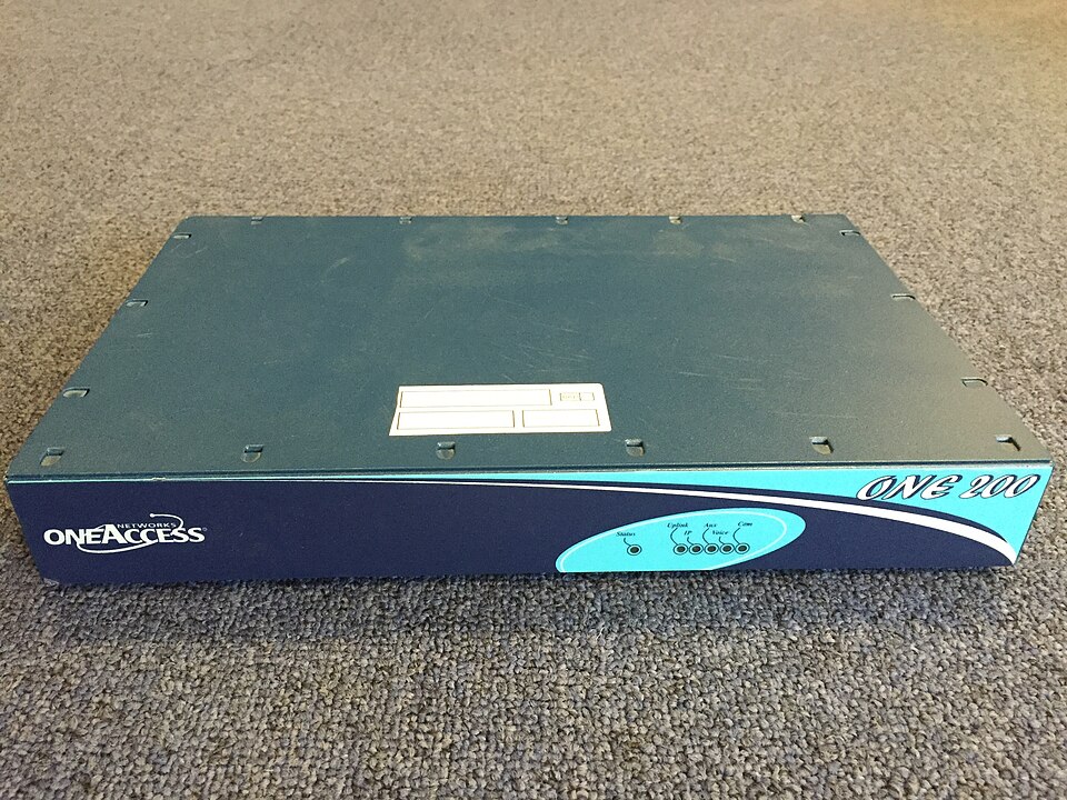 A typical enterprise router (Image: hystiff, CC0, via Wikimedia Commons)
 Single‑mode fiber cable used in ISP backbones (Image: Asurnipal, CC BY-SA 4.0, via Wikimedia Commons)
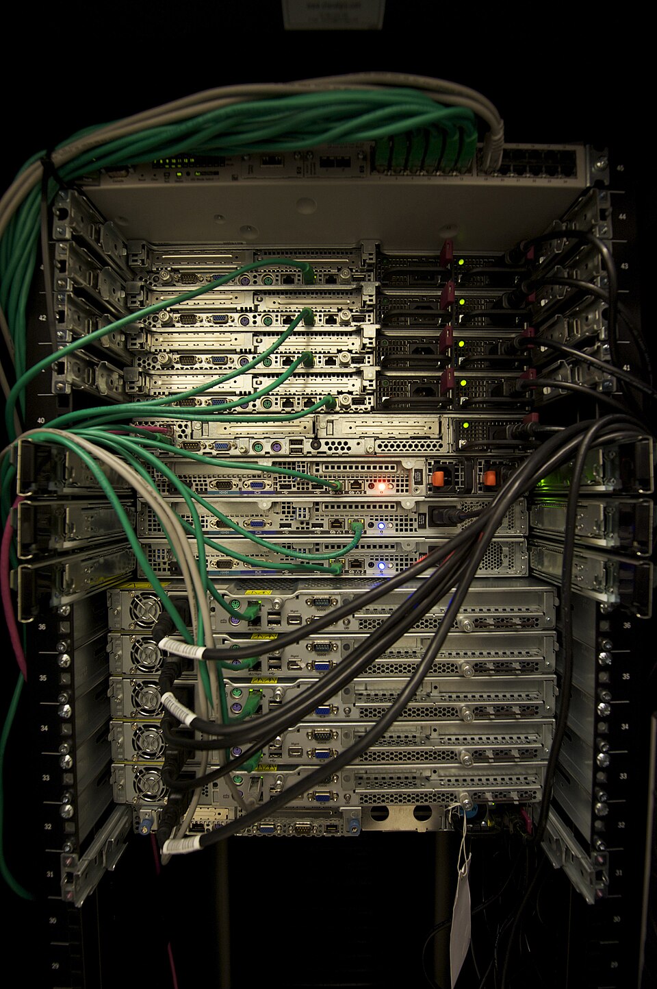 Rack‑mounted servers in a data center (Image: Abigor, CC BY-SA 3.0, via Wikimedia Commons)
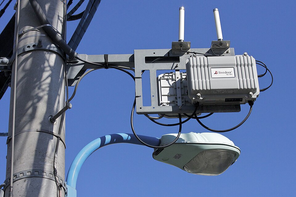 Ncell LTE base station antenna (Image: Maripo GODA, CC BY-SA 3.0, via Wikimedia Commons)
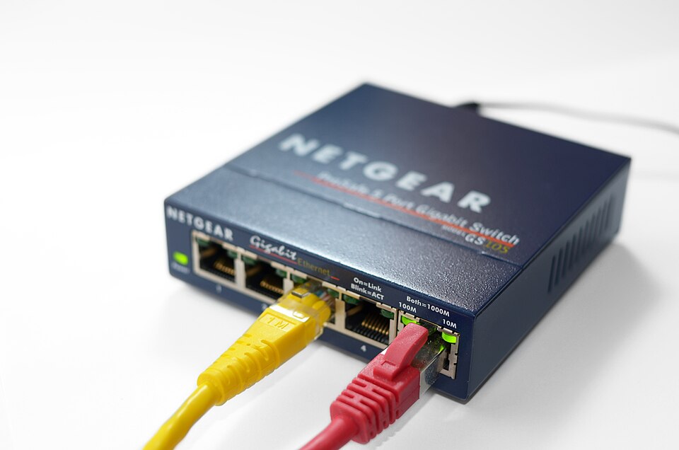 Campus Ethernet switch (Image: Simon A. Eugster, CC BY-SA 3.0, via Wikimedia Commons)
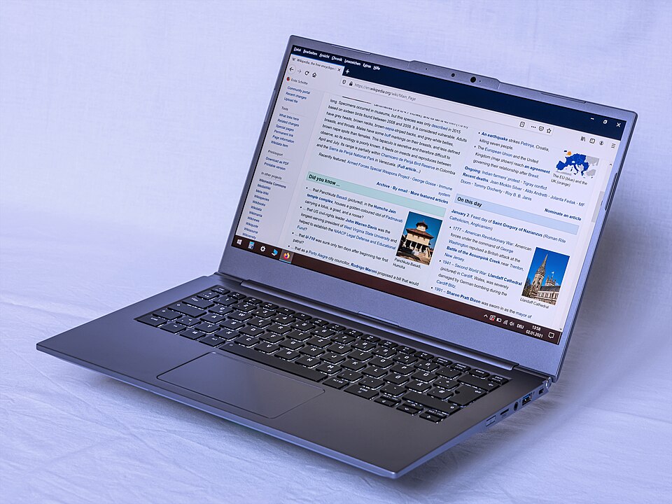 End‑user device in a LAN (Image: A.Savin, FAL, via Wikimedia Commons)
stateDiagram-v2
    [*] --> Idle
    Idle --> Connecting : Client sends SYN
    Connecting --> Established : Server ACKs
    Established --> Closing : Client sends FIN
    Closing --> Closed : Server ACKs FIN
Based on the TU BTTM syllabus for Computer and Information Technology (ITC307), unit 5.
Discussion
Loading…