Basic Electrical EngineeringUnit 18 min read
Charge, Current, Voltage, Power & Resistors
Unit 1 of Basic Electrical Engineering covers fundamental electrical concepts—electric charge, current, voltage, power, resistance, Ohm’s Law, and resistor color coding—with real-world applications in electronics, power systems, and everyday devices.
TAKEAWAYS:
- Electric charge (Coulomb) is the basic property of electrons and protons; current (Amperes) is the flow of charge per second.
- Voltage (Volts) is the potential difference driving current; power (Watts) is the rate of energy transfer.
- Resistance (Ohms) opposes current flow; Ohm’s Law () relates voltage, current, and resistance.
- Resistor color bands encode resistance values and tolerances for circuit design.
- Series/parallel circuits combine resistors differently, affecting total resistance and current distribution.
1. Electric Charge and Current
Electric charge () is a fundamental property of matter, measured in Coulombs (C). It exists in two forms:
- Positive charge (protons, +1.6 × 10⁻¹⁹ C)
- Negative charge (electrons, –1.6 × 10⁻¹⁹ C)
Electric current () is the flow of electric charge through a conductor, measured in Amperes (A): where = charge (C), = time (s).
How Current Flows
- In metals, current flows due to free electrons moving from negative to positive terminals (conventional current flows positive to negative).
- In electrolytes, ions carry charge (e.g., batteries, human nerves).
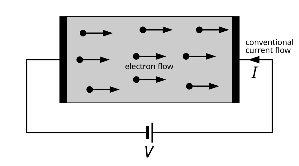 Shows electron flow vs. conventional current direction. (Image: inductiveload, Public domain, via Wikimedia Commons)
Worked Example: Charge Calculation
A current of 5 A flows for 2 minutes. Calculate the total charge transferred. Solution:
2. Voltage (Potential Difference)
Voltage () is the work done per unit charge to move charge between two points, measured in Volts (V): where = work (Joules), = charge (C).
- Battery voltage = electromotive force (emf), the maximum potential difference it can provide.
- Voltage sources (batteries, generators) maintain a fixed potential difference.
Worked Example: Voltage in a Circuit
A 12 V battery moves 3 C of charge. Calculate the work done. Solution:
3. Resistance and Ohm’s Law
Resistance () opposes current flow, measured in Ohms (Ω). It depends on:
- Material (conductivity)
- Length (longer wire = higher resistance)
- Cross-sectional area (thinner wire = higher resistance)
- Temperature (higher temp = higher resistance in metals)
Ohm’s Law relates voltage, current, and resistance: Rearranged forms:
Resistivity and Conductivity
- Resistivity () is a material property: where = length, = area.
- Conductivity () is the inverse of resistivity ().
Worked Example: Resistance Calculation
A copper wire has:
- Length () = 10 m
- Cross-sectional area () = 1 mm² = 1 × 10⁻⁶ m²
- Resistivity () = 1.68 × 10⁻⁸ Ω·m
Calculate its resistance. Solution:
4. Power in Electrical Circuits
Electric power () is the rate of energy transfer, measured in Watts (W): Using Ohm’s Law, power can also be expressed as:
Worked Example: Power Dissipation in a Resistor
A 6 Ω resistor carries 2 A of current. Calculate:
- Power dissipated.
- Energy consumed in 5 minutes.
Solution:
- Energy () = Power × Time =
5. Series and Parallel Resistor Combinations
Resistors can be connected in series or parallel, affecting total resistance ().
Series Connection
- Same current flows through all resistors.
- Total resistance increases:
- Voltage divides across resistors (voltage divider rule).
Parallel Connection
- Same voltage across all resistors.
- Total resistance decreases:
- Current divides (current divider rule).
 Shows current division. (Image: Omegatron, CC BY-SA 3.0, via Wikimedia Commons)
Worked Example: Series-Parallel Circuit
Three resistors (, , ) are connected:
- and in series.
- Combined with in parallel.
- Supply voltage = 12 V.
Calculate:
- Total resistance.
- Current through each resistor.
Solution:
- Total current () =
- Current through =
- Current through and = 2 A (same in series).
6. Resistor Color Coding
Resistors use color bands to indicate:
- Resistance value
- Tolerance (accuracy)
- Temperature coefficient (optional)
Color Code Table:
| Color | Digit | Multiplier | Tolerance |
|---|---|---|---|
| Black | 0 | 10⁰ | - |
| Brown | 1 | 10¹ | ±1% |
| Red | 2 | 10² | ±2% |
| Orange | 3 | 10³ | - |
| Yellow | 4 | 10⁴ | - |
| Green | 5 | 10⁵ | ±0.5% |
| Blue | 6 | 10⁶ | ±0.25% |
| Violet | 7 | 10⁷ | ±0.1% |
| Gray | 8 | 10⁸ | ±0.05% |
| White | 9 | 10⁹ | - |
| Gold | - | 10⁻¹ | ±5% |
| Silver | - | 10⁻² | ±10% |
Example: A resistor with bands Red, Red, Brown, Gold has:
- Resistance = 22 × 10¹ = 220 Ω
- Tolerance = ±5%
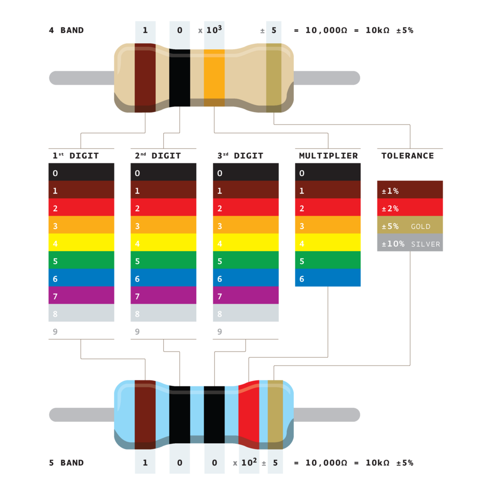 Shows band positions and values. (Image: Adim kassn, CC BY-SA 3.0, via Wikimedia Commons)
7. Real-World Applications
In the Real World
Khalti & eSewa (Digital Payments)
- Uses resistors in circuit boards to limit current to ICs (integrated circuits) and prevent damage.
- Voltage regulators (using resistors) ensure stable power supply to microcontrollers processing transactions.
Ncell & NTC (Telecom & Power Systems)
- Series resistors in antenna circuits match impedance for efficient signal transmission.
- Parallel resistors in voltage dividers measure high voltages safely in power grids.
Pathao (Ride-Hailing App)
- Current sensors (using resistors) monitor battery drain in driver apps.
- Ohm’s Law ensures optimal LED brightness in GPS modules without overheating.
Worked Example: Traffic Light Circuit (Real Scenario)
A traffic light has:
- Red bulb (2 Ω), Yellow bulb (3 Ω), Green bulb (4 Ω) in series.
- Supply voltage = 12 V.
Calculate:
- Total resistance.
- Current through each bulb.
- Power dissipated by the green bulb.
Solution:
- (same for all bulbs in series)
8. Exam Tip
- Memorize Ohm’s Law and power formulas—they appear in every numerical problem.
- Practice resistor color coding—exams often test this quickly (e.g., "A resistor with bands Red, Violet, Brown has resistance ____").
- Understand series vs. parallel:
- Series: Same current, voltages add.
- Parallel: Same voltage, currents add.
- Watch units: Always check if answers are in Ω, A, V, or W.
- Real-world links: Relate problems to batteries, household wiring, or mobile phone circuits for better retention.
Key Formulas Summary:
| Concept | Formula |
|---|---|
| Current | |
| Voltage | |
| Ohm’s Law | |
| Power | |
| Series Resistance | |
| Parallel Resistance | |
| Resistivity |
Based on the PU BE Computer (PU) syllabus for Basic Electrical Engineering, unit 1.
Discussion
Loading…