Basic Electrical EngineeringUnit 711 min read
Single-Phase AC Circuits: Waveforms, Power, Resonance & Practical Applications
Unit 7 of Basic Electrical Engineering covers single-phase AC circuits, including sinusoidal waveforms, power analysis (average, RMS, reactive), series/parallel RLC circuits, resonance phenomena, and practical applications in transformers, motors, and household wiring. This note integrates theory with real-world exampl
Core Concepts: Sinusoidal AC Waveforms and Their Properties
1. Sinusoidal Waveform and Its Parameters
A sinusoidal AC voltage/current varies as , where:
- : Peak (maximum) voltage
- : Angular frequency (rad/s)
- : Phase angle (degrees or radians)
Key Parameters:
| Parameter | Formula | Meaning |
|---|---|---|
| Peak Value | Maximum instantaneous voltage/current. | |
| RMS Value | Effective value (equivalent DC). | |
| Average Value | (for half-wave) | Mean over one cycle. |
| Form Factor | Ratio of RMS to average value. | |
| Peak Factor | Ratio of peak to RMS value. |
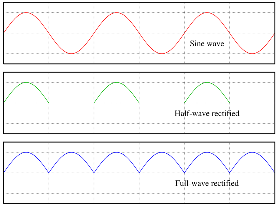 Comparison of full-wave vs. half-wave rectification (Image: Omegatron, CC BY-SA 3.0, via Wikimedia Commons)
2. Power in AC Circuits
a) Instantaneous, Average, and Reactive Power
Instantaneous Power (): . For purely resistive circuits, is always positive. For inductive/capacitive circuits, power oscillates between source and load.
Average Power (): , where is the power factor.
- Unity Power Factor (UPF): (purely resistive load).
- Lagging PF: Inductive load ().
- Leading PF: Capacitive load ().
Reactive Power (): (measured in VAR).
- Represents energy oscillating between source and load (no real work done).
- Apparent Power (): (measured in VA).
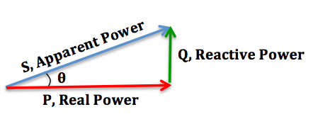 Relationship between P, Q, and S (Image: Wikieditor4321, CC BY-SA 4.0, via Wikimedia Commons)
b) Worked Example: Power Calculation for a Fluorescent Lamp
A 40 W fluorescent lamp operates at 220 V, 50 Hz with a power factor of 0.6 (lagging).
Calculate RMS current: .
Calculate Reactive Power: .
Apparent Power: .
In the Real World
NTC Power Grid (Nepal):
- Idea Used: Three-phase power distribution (though this unit covers single-phase, NTC’s low-voltage grids use single-phase AC for residential areas).
- How: Single-phase transformers step down 11 kV to 230 V for homes. The power factor correction (adding capacitors to offset inductive loads like motors) improves efficiency, reducing reactive power losses.
- Example: During peak hours (6–9 PM), NTC monitors lagging power factors in factories and penalizes low PF to discourage inefficient usage.
WhatsApp Servers (Global):
- Idea Used: AC power conditioning and resonance in filters.
- How: Data centers use active harmonic filters (RLC circuits tuned to specific frequencies) to suppress noise in power supplies. For example, a server’s power supply might have a series resonant circuit at 50/60 Hz to reject voltage spikes, ensuring stable operation for message routing.
Daraz Logistics Warehouses (Nepal):
- Idea Used: Single-phase induction motors and power factor correction.
- How: Conveyor belts in warehouses use single-phase capacitor-start motors (a type of AC motor). To improve efficiency, warehouses install power factor correction capacitors (e.g., 50 µF banks) to compensate for the inductive load of motors, reducing electricity bills by up to 15%.
Series RLC Circuits and Resonance
1. Impedance in RLC Circuits
The total impedance () of a series RLC circuit is: where:
- : Inductive reactance (Ω)
- : Capacitive reactance (Ω)
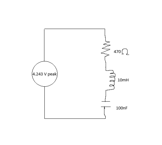 Components: resistor, inductor, capacitor, AC source (Image: Nkkoy, CC0, via Wikimedia Commons)
2. Resonance in Series RLC Circuits
- Resonance Condition: ⇒ .
At resonance:
- Impedance is purely resistive ().
- Current is maximum ().
- Bandwidth () = .
Worked Example: Resonance in a Radio Tuner
A radio tuner has and . Find:
Resonant Frequency: .
Bandwidth if : .
Real-World Tie-In: This principle is used in Nepal’s FM radio stations (e.g., Radio Nepal). The tuner in your radio has a variable capacitor that adjusts resonance to pick up specific frequencies (e.g., 90.8 MHz for Radio Nepal Kathmandu).
Parallel RLC Circuits
1. Admittance and Resonance
- Admittance (): , where , , .
- Resonance Condition: ⇒ (same as series).
At resonance:
- Admittance is purely conductive ().
- Impedance is maximum ().
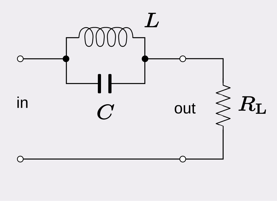 Components: resistor, inductor, capacitor, AC source (Image: SpinningSpark, CC BY-SA 3.0, via Wikimedia Commons)
Power Measurement in AC Circuits
1. Wattmeter Method for Single-Phase Power
Single Wattmeter Method: Measures average power directly: .
- Limitation: Cannot distinguish between active and reactive power.
Two-Wattmeter Method (for 3-phase, but concept applies to single-phase analysis): Uses two wattmeters to measure: Difference from One-Wattmeter Method:
Feature One-Wattmeter Method Two-Wattmeter Method Accuracy Measures only active power Measures both P and Q Complexity Simple Requires two instruments Application Single-phase circuits Three-phase circuits
Practical Applications
1. Transformers (Single-Phase)
- Idea: Step-up/down AC voltages using mutual inductance.
- Example: Nepal’s 11 kV/400 V distribution transformers (used by NTC).
- Turns Ratio: .
- Worked Example: A transformer steps down 11,000 V to 230 V. If the primary has 5,500 turns, find secondary turns: turns.
2. AC Motors (Induction Motors)
- Idea: Rotating magnetic field induces current in the rotor (Lenz’s law).
- Example: Single-phase induction motors in Daraz’s warehouse fans.
- Starting Method: Capacitor-start (creates phase shift for initial torque).
- Power Factor: Typically 0.7–0.8 lagging (requires PF correction).
Exam Tip
What Examiners Look For
Waveform Analysis:
- Always sketch the waveform when asked about half-wave/full-wave rectification.
- Calculate RMS, average, and form factor from the given equation or graph.
- Common Mistake: Forgetting to multiply by for average value of half-wave rectified sine waves.
Power Calculations:
- Memorize the power triangle () and use it to derive relationships.
- For lagging/leading PF, draw the phasor diagram to visualize phase angles.
- Shortcut: If is given, .
Resonance:
- Series resonance: , , current peaks.
- Parallel resonance: , peaks.
- Exam Question: Always check if the circuit is series or parallel before applying resonance conditions.
Practical Scenarios:
- NTC Grid: Relate power factor correction to reducing losses.
- Motors: Explain why capacitors are used in single-phase motors (to create a rotating field).
- Transformers: Link turns ratio to voltage step-up/down in real systems (e.g., NTC transformers).
Diagrams:
- Mandatory: Draw phasor diagrams for RLC circuits to show phase relationships.
- Label everything: Resistors, inductors, capacitors, and angles in phasor diagrams.
Common Pitfalls
- Assuming all AC circuits are resistive: Always consider and .
- Ignoring units: Power in watts (W), reactive power in VAR, apparent power in VA.
- Mixing series/parallel formulas: for series, for parallel.
- Forgetting to convert frequencies: before plugging into or .
Quick Revision Checklist
| Topic | Key Formula/Concept | Real-World Link |
|---|---|---|
| RMS Value | NTC’s 230 V supply is RMS. | |
| Power Factor | WhatsApp servers use UPF for efficiency. | |
| Series Resonance | Radio tuners (FM stations). | |
| Transformer Turns | NTC’s 11 kV/400 V transformers. | |
| Power Triangle | Daraz warehouses correct PF to save cost. |
Final Worked Example: Exam-Style Question
Question: A single-phase load consists of a resistor in series with an inductor . The supply is V. Find: a) The inductive reactance . b) The impedance . c) The RMS current. d) The average power dissipated.
Solution: a) Inductive Reactance: .
b) Impedance: .
c) RMS Current: .
d) Average Power: .
Real-World Tie-In: This is analogous to a single-phase motor (e.g., a water pump in a rural Nepalese household). The inductive load (motor winding) causes a lagging power factor, and the average power calculated here represents the actual mechanical work done by the pump.
Based on the PU BE Computer (PU) syllabus for Basic Electrical Engineering, unit 7.
Discussion
Loading…