InstrumentationUnit 611 min read
Oscilloscopes: Principles, Probes, Triggers, and Waveform Analysis
Unit 6 of Instrumentation explores oscilloscopes—how they display signals, decode voltage vs. time, use probes and triggers, and analyze waveforms. Covers dual-trace operation, bandwidth, and real-world applications in electronics debugging and power systems.
What is an Oscilloscope?
An oscilloscope is a real-time graphical display instrument that visualizes electrical signals (voltage vs. time) on a screen. It is the most versatile tool in electronics labs for:
- Observing AC/DC waveforms (sine, square, triangular).
- Measuring voltage, frequency, phase, and rise/fall times.
- Debugging circuits by analyzing signal behavior.
Key Components of an Oscilloscope
How an Oscilloscope Works: Signal Path
- Input Signal → Probe → Vertical Amplifier (scales voltage).
- Z-Axis Amplifier (intensity control, rarely used).
- Deflection Plates (X and Y) → CRT/LCD Screen (displays waveform).
- Timebase Generator → Horizontal Sweep (moves beam left-to-right).
- Trigger Circuit → Synchronizes sweep to repeating signals.
Waveform Display: Voltage vs. Time
- Y-axis (Vertical): Voltage (controlled by Volts/div knob).
- X-axis (Horizontal): Time (controlled by Time/div knob).
- Trigger Point: Where the sweep starts (adjustable via Trigger Level).
Types of Oscilloscopes
| Type | Description | Advantages | Disadvantages | Example Use Case |
|---|---|---|---|---|
| Analog | Uses CRT, direct beam deflection. | High bandwidth, low latency. | Bulky, expensive, no storage. | Lab experiments, high-speed signals. |
| Digital Storage (DSO) | Samples signal, stores in memory. | Waveform capture, measurements, USB. | Limited bandwidth vs. analog. | Debugging microcontrollers, power electronics. |
| Mixed-Signal | Combines analog + digital channels. | Tests analog + digital signals together. | Complex, expensive. | Embedded systems, IoT devices. |
| Handheld/Pocket | Portable, limited features. | Affordable, portable. | Low resolution, slow sampling. | Field repairs, basic checks. |
| PC-Based | Software-defined oscilloscope. | Cheap, customizable. | Requires PC, limited hardware. | Educational labs, hobbyists. |
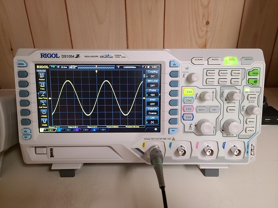 A Rigol DS1054Z showing dual-channel input, touchscreen, and USB port for data transfer. (Image: Draconichiaro, CC BY-SA 4.0, via Wikimedia Commons)
Oscilloscope Probes
Probes connect the oscilloscope to the circuit. Two main types:
Passive Probe (1×/10×)
- 1×: Direct connection (no attenuation).
- 10×: Reduces signal by 10× (standard for most scopes).
- Formula:
- Why? Reduces loading effect on high-impedance circuits.
Active Probe
- Uses FET amplifier for low-capacitance, high-bandwidth signals.
- Used in RF, high-speed digital circuits.
Triggering in Oscilloscopes
Triggering ensures the waveform is stable and repeatable on the screen.
- Trigger Source: CH1, CH2, external, or line.
- Trigger Slope: Rising/falling edge.
- Trigger Level: Voltage at which trigger occurs.
Types of Triggers
| Trigger Type | Description | Use Case |
|---|---|---|
| Edge Trigger | Triggers on rising/falling edge. | Most common (sine, square waves). |
| Pulse Width | Triggers on pulse width. | Digital signals (TTL, CMOS). |
| Video Trigger | Syncs to video signals (NTSC/PAL). | TV, monitor testing. |
| Delay Trigger | Triggers after a set delay. | Analyzing signal delays. |
| Alternate/Automatic | Auto-trigger if no edge detected. | Unstable or single-shot signals. |
Key Measurements with an Oscilloscope
1. Voltage Measurements
- Peak-to-Peak (Vpp): Distance between max and min.
- RMS Voltage: (for sine waves).
- DC Offset: Average voltage level.
Worked Example: A sine wave on CH1 has a Vpp of 8V. Calculate RMS voltage.
2. Time Measurements
- Period (T): Time for one full cycle (sec/div × divisions).
- Frequency (f): .
- Rise/Fall Time: Time to go from 10% to 90% of max voltage.
Worked Example (Real-World Tie-In): In a Nepal Electricity Authority (NEA) power grid, technicians use oscilloscopes to measure voltage sags during load fluctuations. If a waveform shows a period of 20 ms, what is the frequency?
3. Phase Difference
- Measure time delay (Δt) between two signals.
- Phase Angle (θ): .
Dual-Trace Oscilloscopes
- Alternate Mode: CH1 → CH2 → CH1 (fast, but flicker).
- Chop Mode: Rapidly switches between channels (reduces flicker).
- Add/Subtract Mode: Math operations on channels.
When to Use:
- Comparing two signals (e.g., input vs. output of an amplifier).
- Measuring phase difference between signals.
Bandwidth and Sampling Rate
| Parameter | Definition | Impact on Measurement |
|---|---|---|
| Bandwidth | Max frequency the scope can display. | Higher BW = clearer high-frequency signals. |
| Sampling Rate | Samples per second (S/s). | Must be ≥ 2× Nyquist rate (for accurate DSO). |
| Rise Time | Faster rise time = better for high-speed signals. |
Rule of Thumb:
- For accurate measurement, bandwidth ≥ 3× highest signal frequency.
- Example: A 50 MHz scope can measure up to ~17 MHz accurately.
Common Oscilloscope Errors & Fixes
| Error | Cause | Solution |
|---|---|---|
| Waveform not stable | Poor grounding or trigger issues. | Check probe ground, adjust trigger level. |
| Distorted waveform | Incorrect probe compensation. | Adjust probe compensation (usually near tip). |
| No signal on screen | Probe not connected or channel off. | Verify connections, check channel buttons. |
| Flickering display | Low light intensity or CRT issues. | Increase intensity, use LCD/DSO. |
| Incorrect voltage reading | Wrong Volts/div setting. | Recalibrate, use known reference signal. |
In the Real World
Nepal Electricity Authority (NEA) Power Grid Monitoring
- What? Oscilloscopes measure voltage fluctuations and harmonics in the grid.
- How? Technicians use DSOs to analyze transient spikes caused by sudden load changes (e.g., during load shedding).
- Example: A 50 Hz sine wave with a 3% THD (Total Harmonic Distortion) is acceptable; higher values cause equipment damage.
Pathao/E-Sewa Ride-Hailing Systems
- What? Digital oscilloscopes debug GPS signal processing and sensor data (accelerometers, gyroscopes).
- How? Engineers check square-wave pulses from ultrasonic sensors (used in autonomous ride-sharing) to ensure accurate distance measurements.
Ncell/Bhutan Telecom 5G Base Stations
- What? High-bandwidth oscilloscopes (e.g., Tektronix MSO) test RF signals in 5G modems.
- How? They verify signal integrity in millimeter-wave frequencies (24 GHz+) by analyzing eye diagrams (for data integrity).
Exam Tip
What Examiners Look For
Understanding of Block Diagram
- Draw and label the signal path (probe → vertical amp → deflection plates → screen).
- Explain the role of triggering in waveform stability.
Calculations
- Voltage (Vpp, RMS, DC offset) and time (period, frequency, rise time) are high-weightage.
- Phase difference questions often appear—practice with two-channel waveforms.
Probe Compensation
- Know the difference between 1× and 10× probes and when to use each.
- Compensation adjustment is a common practical question.
Trigger Modes
- Be able to select the right trigger type (edge, pulse width, video) for a given scenario.
- Automatic vs. normal trigger—when to use each.
Real-World Applications
- Expect one numerical problem tied to power systems (NEA), telecom (Ncell), or embedded systems (Pathao).
- Example: "A Daraz warehouse uses a motor with a 50 Hz supply. If an oscilloscope shows a 48 Hz waveform, what could be the issue?" (Answer: Frequency drift or load imbalance.)
Common Mistakes to Avoid
- Ignoring probe attenuation (forgetting to divide by 10 for 10× probes).
- Misidentifying axes (confusing Y = voltage vs. X = time).
- Not setting the trigger properly (leading to unstable displays).
- Assuming all oscilloscopes are digital (analog scopes still exist in labs).
Practice Questions (Self-Check)
- A square wave has a period of 1 ms on an oscilloscope set to 0.5 ms/div. How many divisions does it span?
- If a 10× probe reads 5 Vpp, what is the actual signal voltage?
- Why would an engineer use a 100 MHz oscilloscope to debug a 30 MHz Wi-Fi router?
- Sketch the block diagram of an oscilloscope and label the vertical amplifier, timebase, and trigger circuit.
- In a NEA substation, an oscilloscope shows a sine wave with 10% THD. Is this acceptable? Why or why not?
Final Note: Oscilloscopes are the "eyes" of an electronics engineer. Mastering their controls, measurements, and troubleshooting will help you in lab exams, industry jobs (NEA, Ncell, Daraz), and research. Always calibrate probes, set triggers correctly, and double-check settings—small errors lead to wrong conclusions!
Based on the PU BE Computer (PU) syllabus for Instrumentation, unit 6.
Discussion
Loading…