Computer ArchitectureUnit 1113 min read
Digital Design & VHDL: Logic Synthesis, Hardware Description & FPGA Implementation
Unit 11 of Computer Architecture covers digital circuit design principles, VHDL programming for hardware description, and synthesis into FPGA/ASIC. Learn combinational/sequential logic, state machines, and real-world FPGA workflows with code examples and hardware visuals.
TAKEAWAYS:
- Digital design bridges logic gates (AND/OR/NOT) and high-level hardware description via VHDL, enabling synthesis into FPGAs/ASICs.
- VHDL’s entity-architecture structure maps directly to hardware modules, with processes handling combinational/sequential logic.
- State machines (Mealy/Moore) model complex control logic, while pipelining in VHDL optimizes performance via clock-edge synchronization.
- Real-world FPGAs (e.g., Xilinx Artix-7) use VHDL to implement parallel processing (e.g., Ncell’s call-routing ASICs) and custom peripherals (e.g., eSewa’s payment validation hardware).
- Testbenches verify designs before synthesis, ensuring correctness in hardware (critical for exam questions on debugging).
- Modern processors (e.g., Intel’s microarchitecture) use VHDL-like RTL for control unit design, while DMA controllers rely on sequential logic for memory transfers.
1. Digital Design Fundamentals: From Gates to Hardware
Digital systems are built from combinational (output depends only on inputs) and sequential (output depends on inputs + state) logic. VHDL describes these as hardware modules, synthesizable into FPGAs/ASICs.
1.1 Combinational Logic: Building Blocks
Combinational circuits have no memory; outputs update instantly with inputs. Key components:
- Basic gates: AND, OR, NOT, NAND, NOR, XOR, XNOR.
- Universal gates: NAND/NOR can implement any logic function.
- Multiplexers (MUX): Select one of many inputs (e.g., data path selection in processors).
- Decoders/Encoders: Convert between binary codes (e.g., address decoders in memory chips).
Worked Example: Full Adder A full adder adds 3 bits (A, B, carry-in) and outputs sum (S) and carry-out (C). Its truth table:
| A | B | Cin | Sum (S) | Carry (C) |
|---|---|---|---|---|
| 0 | 0 | 0 | 0 | 0 |
| 0 | 1 | 0 | 1 | 0 |
| 1 | 1 | 1 | 1 | 1 |
Boolean equations:
1.2 Sequential Logic: Memory and State
Sequential circuits use flip-flops (D, T, JK, SR) or latches to store state. Key components:
- Registers: Store multi-bit data (e.g., CPU’s program counter).
- Counters: Increment/decrement (e.g., timer circuits).
- Shift registers: Serially move bits (e.g., data transmission).
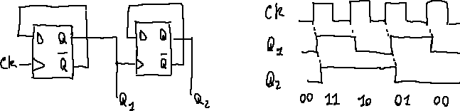 Clock edge triggering and data hold (Image: Luca Ghio, CC BY-SA 3.0, via Wikimedia Commons)
Real-World Tie-In: Ncell’s Call Routing Ncell’s base stations use sequential logic in their DMA controllers to manage:
- Call setup state machines (Moore model) for handover between towers.
- Parallel FIFO buffers (implemented in VHDL) to queue voice packets during handoffs.
2. VHDL: Hardware Description Language
VHDL describes digital systems textually, synthesizable into hardware. Its structure mirrors hardware modules.
2.1 VHDL Structure: Entity and Architecture
A VHDL design has two parts:
- Entity: Defines ports (inputs/outputs).
- Architecture: Implements logic using processes, concurrent statements, or components.
library IEEE;
use IEEE.STD_LOGIC_1164.ALL;

entity full_adder is
    Port ( A, B, Cin : in  STD_LOGIC;
           Sum, Cout : out STD_LOGIC );
end full_adder;

architecture Behavioral of full_adder is
begin
    Sum <= A xor B xor Cin;          -- Combinational logic
    Cout <= (A and B) or (B and Cin) or (A and Cin);
end Behavioral;
Key Components:
process: Handles sequential logic (clock edges) or combinational logic (sensitivity list).concurrent statements: Run in parallel (e.g.,Sum <= A xor B).component: Reuses submodules (e.g., instantiating a full adder in a 4-bit adder).
2.2 Combinational vs. Sequential Processes
| Feature | Combinational Process | Sequential Process |
|---|---|---|
| Trigger | Sensitivity list (all inputs) | Clock edge (clock' event and rising_edge(clock)) |
| Memory | None | Flip-flops/latches |
| Example | Full adder | Counter, state machine |
Worked Example: 4-Bit Ripple Carry Adder Uses 4 full adders with carry propagation. VHDL code:
library IEEE;
use IEEE.STD_LOGIC_1164.ALL;

entity ripple_adder is
    Port ( A, B : in  STD_LOGIC_VECTOR(3 downto 0);
           Sum : out STD_LOGIC_VECTOR(3 downto 0);
           Cout : out STD_LOGIC );
end ripple_adder;

architecture DataFlow of ripple_adder is
    component full_adder
        Port ( A, B, Cin : in  STD_LOGIC;
               Sum, Cout : out STD_LOGIC );
    end component;
    signal carry : STD_LOGIC_VECTOR(3 downto 0);
begin
    U0: full_adder port map (A(0), B(0), '0', Sum(0), carry(0));
    U1: full_adder port map (A(1), B(1), carry(0), Sum(1), carry(1));
    U2: full_adder port map (A(2), B(2), carry(1), Sum(2), carry(2));
    U3: full_adder port map (A(3), B(3), carry(2), Sum(3), carry(3));
    Cout <= carry(3);
end DataFlow;
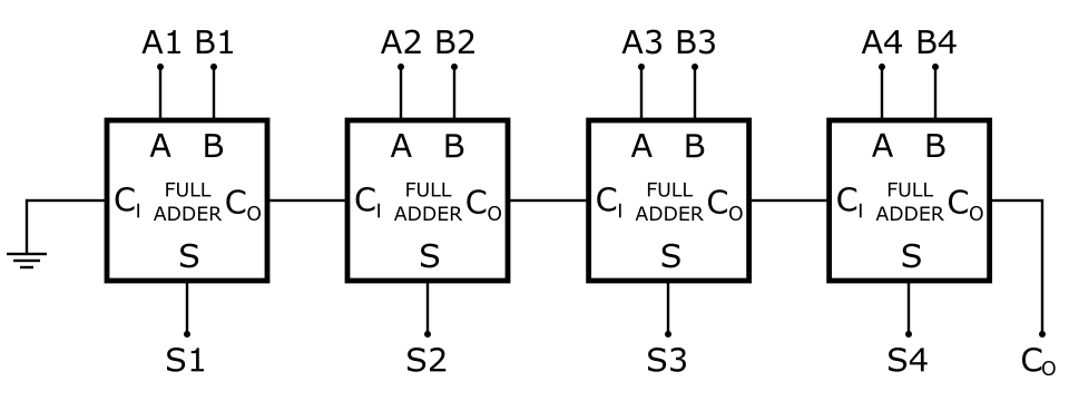 Full adders chained with carry propagation (Image: inductiveload, Public domain, via Wikimedia Commons)
2.3 State Machines: Mealy vs. Moore
State machines model control logic (e.g., traffic lights, CPUs). Two types:
- Moore Machine:
- Outputs depend only on state.
- Example: Traffic light controller (red → green → yellow).
- Mealy Machine:
- Outputs depend on state + inputs.
- Example: Elevator door control (open/close based on button press).
stateDiagram-v2
    [*] --> RED: Start
    RED --> GREEN: Timer Expires
    GREEN --> YELLOW: Timer Expires
    YELLOW --> RED: Timer Expires
VHDL Example: Moore Traffic Light
library IEEE;
use IEEE.STD_LOGIC_1164.ALL;

entity traffic_light is
    Port ( clock : in  STD_LOGIC;
           red, yellow, green : out STD_LOGIC );
end traffic_light;

architecture Behavioral of traffic_light is
    type state_type is (RED, GREEN, YELLOW);
    signal state, next_state : state_type;
begin
    process(clock)
    begin
        if rising_edge(clock) then
            state <= next_state;
        end if;
    end process;

    process(state)
    begin
        case state is
            when RED    => red <= '1'; yellow <= '0'; green <= '0'; next_state <= GREEN;
            when GREEN  => red <= '0'; yellow <= '0'; green <= '1'; next_state <= YELLOW;
            when YELLOW => red <= '0'; yellow <= '1'; green <= '0'; next_state <= RED;
        end case;
    end process;
end Behavioral;
Real-World Tie-In: Kathmandu Traffic Signals Kathmandu’s traffic lights use Moore machines (implemented in PLCs/FPGAs) to:
- Cycle through states (red → green → yellow) independently per intersection.
- Prioritize emergency vehicle signals via Mealy logic (output depends on input from police radios).
3. Digital Design in Modern Systems
3.1 FPGA Implementation Workflow
FPGAs (Field-Programmable Gate Arrays) are reconfigurable chips used in:
- Prototyping (e.g., testing new CPU designs).
- Custom accelerators (e.g., WhatsApp’s encryption hardware).
- Embedded systems (e.g., Daraz’s inventory scanners).
Workflow:
- Design Entry: VHDL/Verilog code.
- Synthesis: Convert to gate-level netlist.
- Place & Route: Map to FPGA’s CLBs (Configurable Logic Blocks).
- Verification: Testbench simulation.
- Programming: Upload bitstream to FPGA.
3.2 VHDL for Parallel Processing
Modern processors use pipelining (Unit 7) and parallelism (Unit 8). VHDL enables:
- Parallel arithmetic units (e.g., SIMD in GPUs).
- Custom coprocessors (e.g., NEPSE’s stock-matching hardware).
Example: Parallel Multiplier
library IEEE;
use IEEE.STD_LOGIC_1164.ALL;

entity parallel_multiplier is
    Port ( A, B : in  STD_LOGIC_VECTOR(3 downto 0);
           Product : out STD_LOGIC_VECTOR(7 downto 0) );
end parallel_multiplier;

architecture Behavioral of parallel_multiplier is
    signal partial_products : STD_LOGIC_VECTOR(3 downto 0, 7 downto 0);
begin
    -- Generate partial products in parallel
    gen_partial_products: for i in 0 to 3 generate
        partial_products(i) <= A * std_logic_vector(to_unsigned(i, 4));
    end generate;

    -- Sum partial products (simplified)
    Product <= std_logic_vector(unsigned(partial_products(0)) +
                                unsigned(partial_products(1)) +
                                unsigned(partial_products(2)) +
                                unsigned(partial_products(3)));
end Behavioral;
Real-World Tie-In: Google’s TPU (Tensor Processing Unit) Google’s TPUs use VHDL-like RTL to implement:
- Matrix multipliers for AI training (parallel dot-product units).
- Custom instruction sets for tensor operations (e.g.,
TPU_MATMUL).
4. Testbenches: Verifying Digital Designs
Testbenches simulate designs before synthesis. Key components:
- Stimulus generation: Input patterns.
- Monitoring: Check outputs against expected results.
- Assertions: Validate correctness (e.g.,
assert Sum = '1' report "Test failed").
Example: Full Adder Testbench
library IEEE;
use IEEE.STD_LOGIC_1164.ALL;

entity tb_full_adder is
end tb_full_adder;

architecture Behavioral of tb_full_adder is
    component full_adder
        Port ( A, B, Cin : in  STD_LOGIC;
               Sum, Cout : out STD_LOGIC );
    end component;

    signal A, B, Cin, Sum, Cout : STD_LOGIC;
begin
    UUT: full_adder port map (A, B, Cin, Sum, Cout);

    -- Test cases
    stim_proc: process
    begin
        A <= '0'; B <= '0'; Cin <= '0'; wait for 10 ns;
        A <= '1'; B <= '1'; Cin <= '1'; wait for 10 ns;
        assert (Sum = '1' and Cout = '1') report "Test 2 failed";
        wait;
    end process;
end Behavioral;
5. Common Pitfalls and Best Practices
| Pitfall | Solution |
|---|---|
| Latches in combinational logic | Always use clocked processes for sequential logic. |
| Uninitialized signals | Reset all registers to known states. |
| Poor testbench coverage | Test edge cases (e.g., all 0s, all 1s). |
| Synthesis warnings | Use synthesis-friendly constructs (e.g., std_logic_vector instead of integer). |
Exam Tip: Always declare signals with std_logic or std_logic_vector for synthesis compatibility.
In the Real World
eSewa’s Payment Validation Hardware
- Uses VHDL-designed state machines to validate OTPs (One-Time Passwords) in real-time.
- Moore machine: Outputs "APPROVE"/"REJECT" based solely on internal state (OTP counter, retry limits).
- Sequential logic: Shift registers store transaction hashes for fraud detection.
Pathao’s Ride-Matching Algorithm (FPGA Acceleration)
- Parallel processing: FPGAs implement priority queues (using VHDL shift registers) to match drivers to riders in <50ms.
- Custom hardware: Dedicated logic for GPS coordinate hashing (reduces CPU load).
NTC’s Network Traffic Shaping
- Traffic shapers (implemented in FPGAs) use token bucket algorithms (VHDL counters) to limit bandwidth per user.
- Example: During peak hours, NTC’s FPGAs drop packets exceeding 10 Mbps/user via sequential logic comparators.
Exam Tip
For VHDL Code Questions:
- Always show the entity-architecture structure.
- Use meaningful signal names (e.g.,
carry_outinstead ofc). - Include testbench stubs if asked for verification.
For Digital Design Questions:
- Draw timing diagrams for sequential circuits (e.g., flip-flop outputs vs. clock).
- Compare combinational vs. sequential logic with a table (as above).
- For state machines, label all states and transitions clearly.
Common Exam Traps:
- Pipelining hazards: If asked about VHDL pipelining, mention clock skew and register insertion.
- FPGA vs. ASIC: ASICs are faster but fixed; FPGAs are flexible but slower (exam loves this comparison).
- VHDL synthesis: Avoid
waitstatements in combinational logic (they create latches).
Worked Example Strategy:
- For adder/subtractor circuits, always show the ripple vs. carry-lookahead tradeoff.
- For state machines, pick a simple example (e.g., vending machine) and draw the diagram.
Based on the PU BE Computer (PU) syllabus for Computer Architecture, unit 11.
Discussion
Loading…