Computer ArchitectureUnit 913 min read
Input/Output Systems: Devices, Interfaces, DMA, and I/O Management
Unit 9 of Computer Architecture explores how computers interact with external devices—from keyboards to hard drives—covering I/O hardware, interfaces, DMA, interrupts, polling, and OS-level I/O management, with real-world examples from eSewa, Daraz, and NTC.
TAKEAWAYS:
- I/O devices communicate with the CPU via interfaces (ports, buses) and require handshaking (control signals like ACK/NAK) to manage data flow.
- DMA (Direct Memory Access) bypasses the CPU for high-speed transfers (e.g., loading a video in YouTube), reducing CPU overhead.
- Interrupts (vs. polling) let devices signal the CPU only when ready, improving efficiency (e.g., keyboard input in WhatsApp typing).
- The I/O subsystem includes hardware (controllers, buffers) and software (device drivers, OS schedulers) to abstract complexity.
- Error handling (parity bits, checksums, retries) ensures data integrity in unreliable channels (e.g., Ncell’s mobile data packets).
- Modern systems use unified I/O architectures (PCIe, USB) and virtualization (e.g., cloud servers hosting Daraz’s backend) to scale performance.
1. Introduction to I/O Systems
I/O (Input/Output) systems enable communication between the CPU and external devices. Unlike memory, I/O devices operate at asynchronous speeds (e.g., a mouse click vs. CPU cycles). The I/O subsystem includes:
- Hardware: Devices (keyboard, printer), controllers, cables, ports.
- Software: Device drivers, OS I/O routines, APIs.
- Interfaces: Protocols (USB, SATA) and physical connections (pins, slots).
Why is I/O critical? Without I/O, a computer would be isolated—no user input, no display, no storage. Real-world example:
eSewa’s payment gateway relies on I/O to read your debit card via a magstripe reader (which uses RS-232/USB interfaces) and send encrypted data to the bank’s server. A failed I/O handshake could freeze the transaction.
2. I/O Hardware Components
A. I/O Devices Classification
Devices are categorized by data transfer mode and function:
| Category | Examples | Transfer Mode | Key Feature |
|---|---|---|---|
| Input | Keyboard, Scanner, Microphone | CPU ← Device | Converts physical signals to digital |
| Output | Monitor, Printer, Speaker | CPU → Device | Converts digital to human-readable |
| Storage | HDD, SSD, USB Drive | Bidirectional (read/write) | Persistent data storage |
| Communication | Modem, Network Card, Wi-Fi Adapter | Bidirectional (real-time) | Connects to other systems |
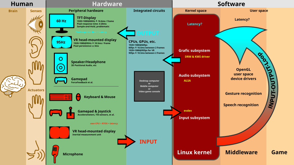 Classification of I/O devices by function and transfer direction (Image: ScotXW, CC BY-SA 3.0, via Wikimedia Commons)
B. I/O Controllers
Devices cannot directly access the CPU’s data bus. Instead, they use controllers (hardware chips) to:
- Buffer data (temporarily store it).
- Convert signals (e.g., analog → digital for a microphone).
- Handle protocols (e.g., USB’s handshake signals).
Example: A USB keyboard controller converts key presses into scan codes, then sends them via USB protocol to the OS.
3. I/O Interfaces and Data Transfer Methods
A. Interfaces: Physical and Logical Connections
Interfaces define how data moves between devices and the CPU. Key types:
| Interface | Type | Example Devices | Speed | Use Case |
|---|---|---|---|---|
| Parallel | Multiple data lines | Printer Port (LPT) | Slow (~1 MB/s) | Legacy printers |
| Serial | Single data line | RS-232, USB | Medium (~10 MB/s) | Modems, old mice |
| USB (Universal) | Plug-and-Play | Keyboard, Flash Drive | Fast (~5 Gbps) | Modern peripherals |
| SATA | High-speed serial | HDD, SSD | Very Fast (~6 Gb/s) | Storage devices |
| PCIe | High-bandwidth | GPU, Network Card | Extremely Fast (~32 GB/s) | Expansion cards |
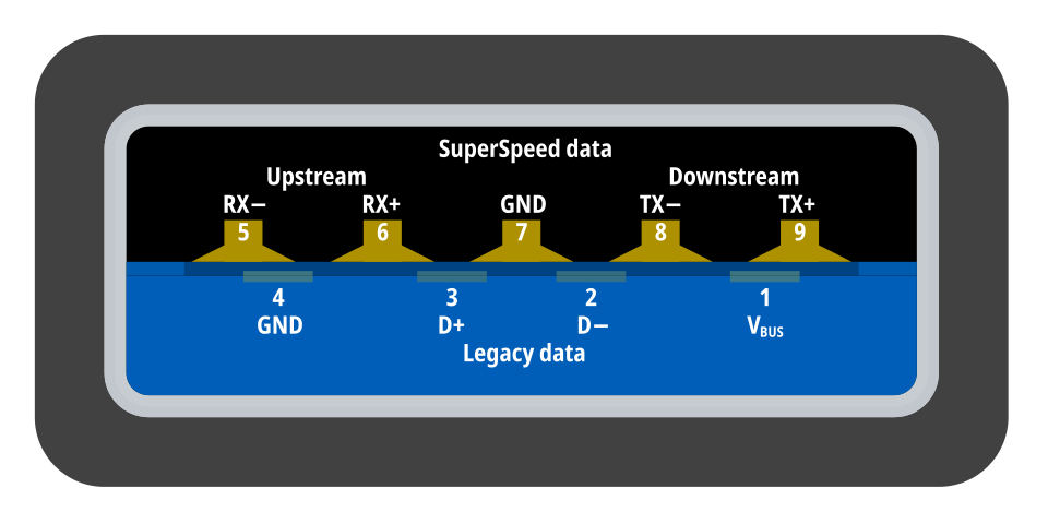 Physical pins and signals in a USB Type-A port (Image: Matthew Wynn, CC BY-SA 4.0, via Wikimedia Commons)
B. Data Transfer Methods
1. Programmed I/O (Polling)
- The CPU repeatedly checks if a device is ready (e.g., "Is the printer paper loaded?").
- Disadvantage: Wastes CPU cycles (like a teacher constantly asking "Are you done?").
- Example: Early computer games polled the joystick for input.
2. Interrupt-Driven I/O
- Devices signal the CPU when ready (via an interrupt request line).
- The CPU saves its state, executes an Interrupt Service Routine (ISR), then resumes.
- Advantage: CPU is free to do other work (e.g., processing Daraz orders while waiting for a payment confirmation).
Mermaid Diagram: Interrupt-Driven I/O Flow
sequenceDiagram
    participant CPU
    participant Device as I/O Device
    participant OS as OS Kernel

    CPU->>Device: Execute instruction (e.g., read keyboard)
    Device-->>CPU: Interrupt (IRQ) sent when key pressed
    CPU->>OS: Save state, jump to ISR
    OS->>Device: Read data via memory-mapped I/O
    OS-->>CPU: Return from interrupt
    CPU->>CPU: Resume normal execution
3. Direct Memory Access (DMA)
- For high-speed devices (e.g., loading a 4K video), the CPU delegates data transfer to a DMA controller.
- Steps:
- Device requests DMA.
- DMA controller transfers data directly to/from memory without CPU involvement.
- CPU gets an interrupt only when done.
Real-World Example:
YouTube’s video buffering uses DMA to stream data from your SSD to the GPU, while your CPU handles other tasks like playing music. Without DMA, your CPU would bottleneck at ~3 GHz vs. the SSD’s 500 MB/s speed.
4. I/O Ports and Addressing
A. Port Addressing
- I/O devices are accessed via port addresses (like memory addresses but for devices).
- Types:
- Memory-Mapped I/O: Devices share the same address space as RAM (e.g., GPU registers).
- Isolated I/O: Devices have separate port addresses (e.g.,
0x3F8for COM1 serial port).
Example Trace: Reading from a Serial Port (COM1)
; x86 Assembly (Isolated I/O)
MOV DX, 0x3F8   ; Load port address of COM1
IN AL, DX      ; Read byte from serial port into AL
B. I/O Handshaking
Devices use control signals to synchronize data transfer:
- ACK (Acknowledge): "I received your data."
- NAK (Not Acknowledge): "Data corrupted; resend."
- BUSY/READY: "I’m not ready yet."
Example: When you drag a file in Daraz, the USB controller sends an ACK to confirm the transfer chunk is received.
5. I/O Software: Drivers and OS Management
A. Device Drivers
- Firmware/software that translates OS commands into hardware-specific operations.
- Example: The Ncell SIM card driver tells the modem how to encode/decode 4G signals.
B. OS I/O Management
The OS handles I/O via:
- System Calls (e.g.,
read(),write()in Linux). - Buffers: Temporary storage for data in transit (e.g., a printer buffer holds pages before printing).
- Scheduling: Deciding which I/O request to process first (e.g., prioritizing a bank transaction over a background download).
Mermaid Diagram: OS I/O Layer Cake
6. Error Handling in I/O
A. Detection Methods
| Method | How It Works | Example |
|---|---|---|
| Parity Bit | Adds a bit to detect odd/even errors | Old RAM modules |
| Checksum | Sums bytes; sender/receiver compare | TCP/IP packets |
| CRC (Cyclic Redundancy Check) | Advanced polynomial error detection | Hard drives, Ethernet |
B. Recovery Strategies
- Retry: Resend data (e.g., failed Ncell SMS delivery).
- Fallback: Use a slower but reliable method (e.g., switching from Wi-Fi to 4G).
- Notify User: Show an error (e.g., "Printer offline" in Microsoft Word).
7. Modern I/O Trends
A. Unified I/O Architectures
- PCIe (Peripheral Component Interconnect Express): Replaces PCI, used for GPUs, SSDs.
- NVMe (Non-Volatile Memory Express): Faster SSD protocol over SATA.
- Thunderbolt: Combines PCIe + DisplayPort for high-speed peripherals.
B. Virtualization and Cloud I/O
- Example: AWS EC2 virtualizes I/O for cloud servers hosting Daraz’s backend.
- Passthrough: Directly assigns a GPU to a VM (used in AI training).
C. I/O in Mobile Devices
- Limited I/O: Phones use low-power interfaces (e.g., eMMC for storage, USB-C for charging).
- Example: Pathao’s app uses Bluetooth Low Energy (BLE) for rider location tracking.
In the Real World
eSewa’s Payment Terminal
- Uses USB HID (Human Interface Device) protocol for card readers.
- Interrupts trigger when you swipe your card, sending data to the eSewa server.
- Error handling: If the bank’s response is NAK (not acknowledged), eSewa retries or asks for another card.
Daraz’s Order Fulfillment
- DMA transfers product images from the warehouse’s SSD to the web server.
- PCIe connects the server’s GPU for rendering high-res product pages.
- Load balancing: The OS schedules I/O requests to avoid bottlenecks during sales events.
NTC’s Fiber-Optic Network
- Uses Synchronous Optical Networking (SONET) for high-speed data transfer between cities.
- Error correction: CRC checks ensure no packet loss in critical communications (e.g., emergency alerts).
Exam Tip
What Examiners Love to Test
Compare Polling vs. Interrupts vs. DMA
- Polling: Simple but inefficient (CPU wasted).
- Interrupts: Efficient for low-speed devices (e.g., keyboard).
- DMA: Best for high-speed devices (e.g., SSDs, network cards).
- Example Question: "Why does a printer use interrupts while an SSD uses DMA?"
Draw and Explain
- I/O handshake signals (ACK/NAK, BUSY/READY).
- DMA transfer flow (device → DMA controller → memory).
- OS I/O layer diagram (application → system call → driver → hardware).
Real-World Applications
- Link concepts to eSewa (interrupts), Daraz (DMA), or NTC (error correction).
- Example: "How would you design the I/O system for a smart traffic light system in Kathmandu?" (Hint: Use interrupts for sensor input, DMA for video feeds.)
Shortcuts for Full Marks
- Memorize these terms: Port addressing, memory-mapped I/O, ISR, DMA burst mode.
- One-liners:
- "DMA reduces CPU overhead by transferring data directly to memory."
- "Interrupts improve efficiency by letting devices signal the CPU only when needed."
Common Pitfalls
- Don’t confuse:
- Polling (CPU checks device) vs. Interrupts (device tells CPU).
- Serial (1 bit at a time) vs. Parallel (multiple bits at once).
- Avoid vague answers: Instead of "I/O is important", say "I/O enables user interaction and data persistence, e.g., a keyboard’s scan codes are read via interrupts to update the OS input buffer."
- Don’t confuse:
Practice Question with Worked Example
Question: "Explain how a USB flash drive communicates with the CPU using DMA. Include a step-by-step trace and a diagram."
Answer:
- User inserts USB drive → OS detects new device via USB root hub interrupt.
- DMA Controller Initialization:
- OS configures DMA controller with:
- Source: USB drive buffer.
- Destination: Main memory (e.g.,
0x80000000). - Transfer size: 128 MB (file size).
- OS configures DMA controller with:
- DMA Transfer:
- USB drive sends data in 64-byte chunks (USB packet size).
- DMA controller writes each chunk to memory without CPU involvement.
- Completion Interrupt:
- After transfer, DMA sends an interrupt to the CPU.
- CPU updates file system metadata (e.g., updates directory entry in NTFS).
Mermaid Diagram: USB DMA Transfer
sequenceDiagram
    participant User
    participant OS
    participant DMA
    participant USB as USB Drive
    participant Memory

    User->>OS: Insert USB drive
    OS->>DMA: Configure DMA (source=USB, dest=Memory, size=128MB)
    loop DMA Transfer
        USB->>DMA: Send 64-byte chunk
        DMA->>Memory: Write chunk
    end
    DMA-->>OS: Interrupt (Transfer Complete)
    OS->>Memory: Update file system
Worked Example Tie-In:
Nepal Stock Exchange (NEPSE) Data Feed NEPSE’s real-time stock prices are streamed via DMA from the exchange’s server to traders’ terminals. If DMA weren’t used, the CPU would bottleneck at ~3 GHz while trying to process 10,000+ price updates per second. Instead, the DMA controller handles the data transfer, and the CPU only processes the final updated values.
Based on the PU BE Computer (PU) syllabus for Computer Architecture, unit 9.
Discussion
Loading…