Business Data Communication and NetworkingUnit 414 min read
Data Link Layer: Framing, MAC, LANs, Ethernet, Switches & Error Control
Unit 4 of Business Data Communication and Networking covers the Data Link Layer’s core functions—framing, MAC addressing, LAN technologies (Ethernet, Wi-Fi), switching, error control (CRC, Hamming), and real-world applications in Nepal’s networks (eSewa, NTC, Daraz). It explains how devices communicate on the same netw
Core Functions of the Data Link Layer
The Data Link Layer (Layer 2) is the second layer of the OSI model. It sits between the Physical Layer (raw bits) and the Network Layer (logical addressing). Its three main jobs are:
- Framing: Breaking data into manageable chunks (frames) and adding control information.
- MAC (Media Access Control): Managing how devices share the same physical medium (e.g., Ethernet cable, Wi-Fi channel).
- Error Control: Detecting and correcting errors introduced by the Physical Layer.
mindmap
  root((Data Link Layer))
    Framing
      Adds headers/trailers
      Defines frame boundaries
      Example: Ethernet II frame
    MAC Sublayer
      Logical Link Control (LLC)
      Media Access Control (MAC)
      CSMA/CD (Ethernet)
      CSMA/CA (Wi-Fi)
    Error Control
      Parity bits
      CRC (Cyclic Redundancy Check)
      Hamming codes
1. Framing: Structuring Data into Frames
Why Framing?
- The Network Layer sends packets, but the Data Link Layer must break them into frames for transmission.
- Frames include:
- Header: Source/Destination MAC addresses, protocol type (e.g., IPv4/IPv6).
- Payload: Data from the Network Layer.
- Trailer: Error-checking bits (e.g., CRC).
How Frames Are Delimited
Three common methods:
| Method | Description | Example |
|---|---|---|
| Character Count | Counts characters in the frame (inefficient, prone to errors). | Old X.25 networks |
| Flag Bytes | Uses a unique flag (e.g., 01111110) to mark start/end. |
HDLC, PPP |
| Byte Stuffing | Escapes special characters (e.g., 01111110 → 01111101 01111110). |
Ethernet (rarely used now) |
Ethernet II Frame Format (Most Common)
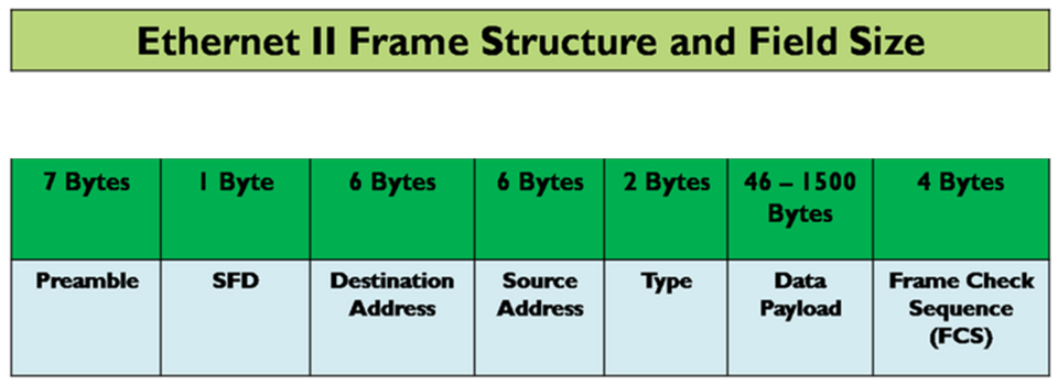
- Preamble (7 bytes): Synchronizes sender/receiver clocks (
10101010). - SFD (1 byte): Start Frame Delimiter (
10101011). - Destination MAC (6 bytes): Who the frame is for (e.g.,
00:1A:2B:3C:4D:5E). - Source MAC (6 bytes): Sender’s MAC address.
- Type (2 bytes): Protocol (e.g.,
0800= IPv4). - Payload (46–1500 bytes): Data from Network Layer (minimum padding if <46 bytes).
- CRC (4 bytes): Error detection (explained later).
Worked Example: eSewa Payment Request When you pay a bill via eSewa:
- Your phone sends an IP packet to eSewa’s server.
- The Data Link Layer at your router encapsulates it into an Ethernet frame.
- The frame’s Destination MAC is the router’s MAC (
AA:BB:CC:11:22:33). - The Source MAC is your phone’s Wi-Fi adapter (
55:66:77:88:99:00). - The frame travels through NTC’s fiber-optic network until it reaches eSewa’s server.
2. MAC Sublayer: Controlling Access to Shared Media
The MAC (Media Access Control) sublayer manages how devices share a shared medium (e.g., Ethernet cable, Wi-Fi channel). Two key protocols:
A. CSMA/CD (Carrier Sense Multiple Access with Collision Detection)
Used in Ethernet (wired networks). How it works:
- Carrier Sense: Device checks if the medium is idle.
- Transmit if idle: If free, sends data.
- Collision Detection: If two devices transmit simultaneously, they detect a collision (signal distortion).
- Backoff Algorithm: Devices wait a random time (
0to2^n-1slots) before retrying.
sequenceDiagram
    participant A as Device A
    participant B as Device B
    participant Medium as Shared Medium
    A->>Medium: Sends data (idle)
    B->>Medium: Sends data (collision!)
    Medium-->>A: Detects collision
    Medium-->>B: Detects collision
    A->>A: Waits random time (e.g., 5 slots)
    B->>B: Waits random time (e.g., 3 slots)
    A->>Medium: Retries transmission
Advantages/Disadvantages:
| Pros | Cons |
|---|---|
| Simple to implement. | Inefficient in high traffic. |
| Works well in low-density networks. | Collisions waste bandwidth. |
| No central controller needed. | Performance degrades with more devices. |
Real-World Example: Kathmandu Traffic (Analogy)
- Imagine two cars (
Device AandDevice B) trying to merge onto the same road (shared medium). - If both accelerate at once (
collision), they must wait a random time before retrying (backoff). - In Ethernet, collisions are rare because switches (not hubs) are used today.
B. CSMA/CA (Carrier Sense Multiple Access with Collision Avoidance)
Used in Wi-Fi (802.11). Key Differences from CSMA/CD:
- No collisions in Wi-Fi? Not quite—Wi-Fi uses ACK (Acknowledgement) to confirm receipt.
- Interframe Spaces (IFS): Different waiting times for priority (e.g., management frames get priority).
- RTS/CTS (Request to Send/Clear to Send): Used in busy networks to reserve the channel.
flowchart TD
    A["Device wants to send"] --> B["Senses channel idle"]
    B --> C["Waits DIFS (Distributed IFS)"]
    C --> D["Sends RTS (Request to Send)"]
    D --> E["AP sends CTS (Clear to Send)"]
    E --> F["Device sends data"]
    F --> G["AP sends ACK"]
Worked Example: Pathao Rider Order When a Pathao rider accepts your order:
- Your phone sends a data frame to Pathao’s server via Wi-Fi.
- The AP (Access Point) at your location uses CSMA/CA to avoid collisions with other devices (e.g., neighbors streaming YouTube).
- If the channel is busy, your phone waits (
DIFS) and may use RTS/CTS to reserve the channel.
3. LAN Technologies: Ethernet and Wi-Fi
A. Ethernet (IEEE 802.3)
- Standard: Defines wired LANs (copper/fiber).
- Topologies:
- Bus: All devices share a single cable (obsolete).
- Star: Devices connect to a switch/hub (most common today).
- Ring: Devices in a loop (rare, e.g., FDDI).
- Mesh: Every device connected to every other (expensive, used in critical networks).
graph TD
    subgraph Star Topology (Most Common)
        Switch["Switch"]
        PC1["PC 1"] --> Switch
        PC2["PC 2"] --> Switch
        PC3["PC 3"] --> Switch
    end
Ethernet Standards:
| Standard | Speed | Medium | Use Case |
|---|---|---|---|
| 10BASE-T | 10 Mbps | Cat5 cable | Old offices |
| 100BASE-TX | 100 Mbps | Cat5 cable | Home networks |
| 1000BASE-T | 1 Gbps | Cat5e/6 cable | Modern offices |
| 10GBASE-T | 10 Gbps | Cat6/6a cable | Data centers |
| 100GBASE-SR | 100 Gbps | Fiber (SFP+) | NTC’s backbone networks |
Real-World Example: NTC’s Fiber-Optic Network
- NTC uses 100GBASE-SR fiber-optic cables to connect major cities.
- Switches (not hubs) ensure no collisions—each device gets a dedicated path.
B. Wi-Fi (IEEE 802.11)
- Uses radio waves (2.4 GHz, 5 GHz, 6 GHz).
- Key Standards:
- 802.11b: 11 Mbps (2.4 GHz).
- 802.11g: 54 Mbps (2.4 GHz).
- 802.11n: 600 Mbps (MIMO, 2.4/5 GHz).
- 802.11ac: 3.5 Gbps (5 GHz, MU-MIMO).
- 802.11ax (Wi-Fi 6): 9.6 Gbps (6 GHz, OFDMA).
Wi-Fi Frame Types:
| Type | Description |
|---|---|
| Management | Beacon, Probe Request, Association Request (e.g., connecting to "Ncell_WiFi"). |
| Control | RTS, CTS, ACK (avoiding collisions). |
| Data | Actual payload (e.g., streaming YouTube). |
Worked Example: Daraz Shopping on Mobile Data
- Your phone sends a data frame to Daraz’s server via Ncell’s 4G/LTE network.
- The MAC layer uses CSMA/CA to avoid collisions with other users.
- If the signal is weak, your phone may switch to 5 GHz (802.11ac) for faster speeds.
4. Switches vs. Hubs: Why Switches Rule
| Feature | Hub | Switch |
|---|---|---|
| Operation | Broadcasts to all ports. | Forwards only to destination. |
| Collision Domain | One per hub. | One per port. |
| Bandwidth | Shared (e.g., 10 Mbps split among 4 PCs = 2.5 Mbps each). | Dedicated (10 Mbps per port). |
| Intelligence | Dumb (Layer 1). | Smart (Layer 2, uses MAC table). |
How a Switch Learns MAC Addresses:
- A frame arrives at Port 1 with Source MAC = AA:BB:CC.
- The switch adds to its MAC table:
AA:BB:CC → Port 1. - If a frame’s Destination MAC is in the table, it forwards only to that port.
- If not, it floods (sends to all ports except the incoming one).
sequenceDiagram
    participant PC1
    participant Switch
    participant PC2
    PC1->>Switch: Frame (Dest: PC2, Src: PC1)
    Switch->>Switch: Learns PC1: Port 1
    Switch->>PC2: Forwards frame
    PC2->>Switch: Replies (Dest: PC1, Src: PC2)
    Switch->>Switch: Learns PC2: Port 2
    Switch->>PC1: Forwards reply
Real-World Example: Nabil Bank’s Internal Network
- Nabil Bank uses Layer 2 switches to connect ATMs, branches, and servers.
- No collisions: Each ATM gets a dedicated 1 Gbps link to the switch.
- Security: Switches can be configured to block unknown MAC addresses.
5. Error Control: Detecting and Correcting Errors
The Data Link Layer ensures data integrity using:
- Parity Check: Simple but weak (detects odd/even errors).
- CRC (Cyclic Redundancy Check): Most widely used (e.g., Ethernet, Wi-Fi).
- Hamming Codes: Corrects single-bit errors (used in memory, CDs).
A. CRC (Cyclic Redundancy Check)
How it works:
- Sender divides data by a generator polynomial (e.g.,
x^16 + x^12 + x^5 + 1for Ethernet). - Remainder is appended as the CRC field in the frame.
- Receiver divides the entire frame by the same polynomial.
- If remainder =
0→ No error. - If remainder ≠
0→ Error detected (frame discarded).
- If remainder =
Example: CRC-4 (Simplified)
- Data:
101100 - Generator:
1001(CRC-4) - Sender:
1011000000÷1001= Quotient1101, Remainder100→ Append100.- Transmitted:
101100100.
- Receiver:
101100100÷1001= Remainder0→ No error.
Worked Example: Ncell’s SMS Delivery
- Your phone sends an SMS to a friend via Ncell’s GSM network.
- The Data Link Layer adds a CRC to detect errors in transmission.
- If the CRC fails, Ncell retries or asks you to resend.
B. Hamming Codes (Error Correction)
- Adds extra bits to correct single-bit errors.
- Example:
(7,4) Hamming Code(4 data bits + 3 parity bits).
| Data (4 bits) | Parity Bits (P2 P1 P0) | Transmitted Code |
|---|---|---|
1011 |
1 0 1 |
1 0 1 1 0 1 1 |
How it corrects errors:
- If
P0fails, the error is in bit 1. - If
P1fails, the error is in bit 3 or 5. - The receiver flips the erroneous bit.
Real-World Example: CDs and DVDs
- CDs use Reed-Solomon codes (a type of Hamming-like code) to correct scratches.
In the Real World
eSewa Payments
- When you pay a bill, your phone’s Wi-Fi/Ethernet uses CSMA/CA (if Wi-Fi) or switches (if wired) to send frames to eSewa’s server.
- CRC ensures no corruption in the transaction data.
NTC’s Fiber-Optic Backbone
- NTC uses 100GBASE-SR Ethernet switches to connect cities.
- MAC addressing ensures each frame reaches the correct router.
- CRC detects errors in high-speed data transmission.
Daraz Order Fulfillment
- When you place an order, Daraz’s data center switches forward your request to the warehouse system.
- CSMA/CD (if using old Ethernet) or CSMA/CA (if Wi-Fi) manages access.
- Hamming codes (in memory) prevent errors in inventory databases.
Exam Tip
What Examiners Love to Test
- Frame Structure: Draw and label an Ethernet II frame. Know the minimum/maximum payload size (46–1500 bytes).
- MAC vs. IP Addressing:
- MAC = Hardware address (e.g.,
00:1A:2B:3C:4D:5E). - IP = Logical address (e.g.,
192.168.1.1).
- MAC = Hardware address (e.g.,
- CSMA/CD vs. CSMA/CA:
- CSMA/CD: Used in Ethernet (wired), detects collisions.
- CSMA/CA: Used in Wi-Fi, avoids collisions via RTS/CTS.
- Switch vs. Hub:
- Switch = No collisions, dedicated bandwidth.
- Hub = Collisions, shared bandwidth.
- CRC Calculation: Be able to compute a simple CRC (e.g., CRC-4).
- Real-World Scenarios:
- Explain how Ncell’s 4G uses CSMA/CA.
- Describe how Nabil Bank’s ATM network uses switches.
Common Mistakes to Avoid
- Confusing MAC addressing (Layer 2) with IP addressing (Layer 3).
- Forgetting that Wi-Fi uses CSMA/CA, not CSMA/CD.
- Drawing an Ethernet frame without CRC or incorrect field sizes.
- Assuming hubs are still used (they’re obsolete—examiners may trick you!).
High-Scoring Answer Tips
- Draw diagrams: Always include a frame structure, CSMA/CD/CA flowchart, or switch MAC table.
- Relate to Nepal: Mention NTC, Ncell, eSewa, Daraz, or bank networks in examples.
- Compare technologies: Use tables (e.g., Ethernet vs. Wi-Fi, Hub vs. Switch).
- Calculate CRC: Even a simple example (e.g., CRC-4) can fetch marks.
mindmap
  root((Exam Focus Areas))
    Frame Structure
      Ethernet II format
      Minimum/maximum payload
    MAC vs IP
      MAC: Hardware, 48-bit, e.g., 00:1A:2B:3C:4D:5E
      IP: Logical, 32/128-bit, e.g., 192.168.1.1
    CSMA/CD vs CA
      CD: Collision Detection (Ethernet)
      CA: Collision Avoidance (Wi-Fi, RTS/CTS)
    Switch vs Hub
      Switch: No collisions, dedicated bandwidth
      Hub: Collisions, shared bandwidth
    CRC Calculation
      Example: CRC-4 for 101100
    Real-World Examples
      NTC fiber network
      eSewa payment frames
      Daraz order processing
Based on the TU BITM syllabus for Business Data Communication and Networking (IT240), unit 4.
Discussion
Loading…