Networking and System AdministrationUnit 514 min read
Network Config: IP, Routing, Subnetting, Topologies & Protocols
Unit 5 of Networking and System Administration covers IP addressing, subnetting, routing (static/dynamic), network topologies, and protocols (TCP/IP, ICMP, ARP). It explains how devices communicate, how to design efficient networks, and how to configure interfaces and routes in Linux/Windows.
TAKEAWAYS:
- Understand IPv4/IPv6 addressing, subnetting, and CIDR notation to design and troubleshoot networks.
- Differentiate static vs. dynamic routing and know when to use each (e.g., small networks vs. ISPs).
- Visualize network topologies (star, mesh, bus) and their pros/cons for real-world deployments (e.g., NTC’s backbone vs. a home Wi-Fi).
- Master TCP/IP protocol stack layers and how protocols like ICMP, ARP, and DNS enable communication.
- Configure Linux/Windows interfaces (IP, subnet mask, gateway) and verify connectivity using
ping,traceroute, andip route. - Apply subnetting rules to divide a network into subnets (e.g., splitting a class C address for a university’s departments).
1. IP Addressing and Subnetting: The Foundation of Network Communication
Every device on a network needs a unique identifier: an IP address. IPv4 uses 32-bit addresses (e.g., 192.168.1.1), while IPv6 uses 128-bit addresses (e.g., 2001:0db8::1). Subnetting divides a network into smaller subnets to improve efficiency and security.
1.1 IP Address Classes (Legacy)
IPv4 addresses are divided into classes based on the first octet:
| Class | Range | Default Subnet Mask | Usage Example |
|---|---|---|---|
| A | 1–126 | 255.0.0.0 | Large organizations (e.g., NTC) |
| B | 128–191 | 255.255.0.0 | Medium networks (e.g., universities) |
| C | 192–223 | 255.255.255.0 | Small networks (e.g., home Wi-Fi) |
| D | 224–239 | Multicast | Video streaming (e.g., YouTube) |
| E | 240–255 | Reserved | Experimental |
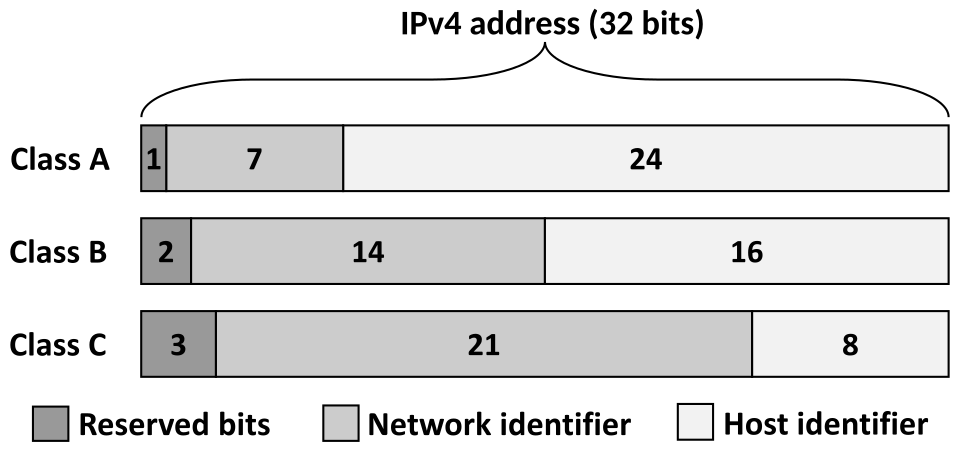 Legacy IPv4 classful addressing ranges (Image: Michel Bakni, CC BY-SA 4.0, via Wikimedia Commons)
1.2 Subnetting: Dividing Networks Efficiently
Subnetting splits a network into smaller subnets using a subnet mask. The subnet mask defines which bits are for the network portion and which are for the host portion.
Example: Subnetting a Class C Network (192.168.1.0/24)
- Given: Network
192.168.1.0with subnet mask255.255.255.0(8 host bits). - Goal: Create 4 subnets with at least 14 hosts each.
- Steps:
- Borrows bits: Need 2 bits for 4 subnets (
2^2 = 4). - New subnet mask:
255.255.255.192(26 bits,/26). - Subnet IDs:
192.168.1.0(00)192.168.1.64(01)192.168.1.128(10)192.168.1.192(11)
- Host ranges:
- Subnet 1:
192.168.1.1–192.168.1.62 - Subnet 2:
192.168.1.65–192.168.1.126 - (Repeat for others.)
- Subnet 1:
- Borrows bits: Need 2 bits for 4 subnets (
Worked Example: NTC’s Backbone Network
NTC uses a /16 network (10.0.0.0/16) for its backbone. To connect 5 regional offices, they subnet it into /24 subnets:
- Subnet 1:
10.0.1.0/24(Kathmandu) - Subnet 2:
10.0.2.0/24(Pokhara) - ...
- Subnet 5:
10.0.5.0/24(Biratnagar)
1.3 CIDR Notation and Variable-Length Subnet Masking (VLSM)
CIDR (Classless Inter-Domain Routing) uses slash notation (e.g., /24) to represent subnet masks. VLSM allows flexible subnet sizing based on host needs.
Example: VLSM for a University Network
| Department | Hosts Needed | Subnet Mask | Subnet ID |
|---|---|---|---|
| Computer Lab | 30 | /27 | 192.168.1.0/27 |
| Admin Office | 10 | /28 | 192.168.1.32/28 |
| Library | 20 | /28 | 192.168.1.48/28 |
| Guest Wi-Fi | 50 | /26 | 192.168.1.64/26 |
Mermaid Diagram: CIDR Subnetting
mindmap
  root((192.168.1.0/24))
    CIDR Subnetting
      /27 (30 hosts)
        192.168.1.0/27
      /28 (14 hosts)
        192.168.1.32/28
        192.168.1.48/28
      /26 (62 hosts)
        192.168.1.64/26
2. Network Topologies: How Devices Are Connected
Topology defines how devices (computers, routers, switches) are physically or logically connected. The choice affects scalability, cost, and fault tolerance.
2.1 Common Topologies
| Topology | Description | Pros | Cons | Example Use Case |
|---|---|---|---|---|
| Star | All devices connect to a central hub/switch. | Easy to manage, fault isolation | Single point of failure | Home Wi-Fi, office LAN |
| Bus | All devices share a single cable (e.g., Ethernet). | Low cost | Difficult to troubleshoot | Legacy networks (rare now) |
| Ring | Devices connected in a closed loop; data travels in one direction. | Equal bandwidth, no collisions | Failure in one node breaks all | Token Ring (obsolete) |
| Mesh | Every device connected to every other device (full mesh) or some (partial). | High redundancy, fast recovery | Expensive, complex | NTC’s core network, ISPs |
| Hybrid | Combination of topologies (e.g., star + bus). | Flexible | Complex management | University campus network |
Real-World Example: Pathao’s Delivery Network Pathao uses a hybrid topology:
- Star topology for rider-to-server communication (each rider’s phone connects to a central server).
- Mesh topology for backup routes if a server fails (redundancy).
3. Routing: How Data Finds Its Way
Routing determines the path packets take from source to destination. Routers use routing tables to make decisions.
3.1 Static vs. Dynamic Routing
| Feature | Static Routing | Dynamic Routing |
|---|---|---|
| Configuration | Manually configured by admin | Automatically updated (protocols) |
| Complexity | Simple, low overhead | Complex, higher CPU usage |
| Scalability | Poor (not for large networks) | Excellent (adapts to changes) |
| Example Protocols | N/A (manual) | OSPF, BGP, RIP |
| Use Case | Small networks (e.g., home router) | ISPs, large enterprises (e.g., NTC) |
Example: Configuring Static Routes in Linux
# Add a static route to 192.168.2.0/24 via gateway 192.168.1.2
sudo ip route add 192.168.2.0/24 via 192.168.1.2

# Make it persistent (add to /etc/network/interfaces or netplan)
echo "192.168.2.0/24 via 192.168.1.2" | sudo tee -a /etc/network/interfaces
Mermaid Diagram: Static Routing Example
graph TD
    A["PC1: 192.168.1.10"] -->|"Destination: 192.168.2.50"| B["Router1: 192.168.1.1"]
    B -->|"Route: 192.168.2.0/24 via 192.168.1.2"| C["Router2: 192.168.1.2"]
    C --> D["PC2: 192.168.2.50"]
3.2 Dynamic Routing Protocols
| Protocol | Type | Use Case | Metric Used |
|---|---|---|---|
| RIP | Distance-vector | Small networks (max 15 hops) | Hop count |
| OSPF | Link-state | Large enterprises (e.g., NTC) | Cost (bandwidth, delay) |
| BGP | Path-vector | ISPs (e.g., Ncell ↔ NTC) | Path attributes |
Example: OSPF in NTC’s Network NTC uses OSPF to dynamically route traffic between regional offices. If a link fails (e.g., Kathmandu-Pokhara fiber cut), OSPF recalculates routes in seconds.
4. TCP/IP Protocol Suite: The Rules of Network Communication
The TCP/IP model has 4 layers (vs. OSI’s 7). Each layer has protocols for specific functions.
Mermaid Diagram: TCP/IP vs. OSI Layers
flowchart TD
    subgraph OSI Model
        A["Application"] --> B["Presentation"] --> C["Session"] --> D["Transport"] --> E["Network"] --> F["Data Link"] --> G["Physical"]
    end
    subgraph TCP/IP Model
        H["Application"] --> I["Transport"] --> J["Internet"] --> K["Network Access"]
    end
4.1 Key Protocols by Layer
| Layer | Protocol | Function | Example |
|---|---|---|---|
| Application | HTTP/HTTPS | Web communication (e.g., Daraz, Google) | GET /product/123 HTTP/1.1 |
| SMTP | Email (e.g., Gmail, Ncell mail) | HELO, MAIL FROM |
|
| DNS | Domain name resolution (e.g., esewa.com.np → IP) |
A record, MX record |
|
| Transport | TCP | Reliable, connection-oriented (e.g., file downloads) | 3-way handshake, acknowledgments |
| UDP | Fast, connectionless (e.g., video streaming, VoIP) | No handshake, no retransmission | |
| Internet | IP | Logical addressing and routing | IPv4/IPv6 packets |
| ICMP | Error reporting and diagnostics (e.g., ping, traceroute) |
Echo Request/Reply |
|
| ARP | Maps IP → MAC address (e.g., arp -a in Linux) |
Broadcast request | |
| Network Access | Ethernet | Physical transmission (e.g., Wi-Fi, fiber) | MAC frames, CSMA/CD |
Worked Example: How YouTube Uses TCP/IP
- Application Layer: You type
youtube.com→ DNS resolves it to142.250.190.46. - Transport Layer: Your browser uses TCP to establish a connection (3-way handshake).
- Internet Layer: IP packets are routed via ISPs (e.g., Ncell → Google’s CDN).
- Network Access: Ethernet/Wi-Fi transmits frames to your device.
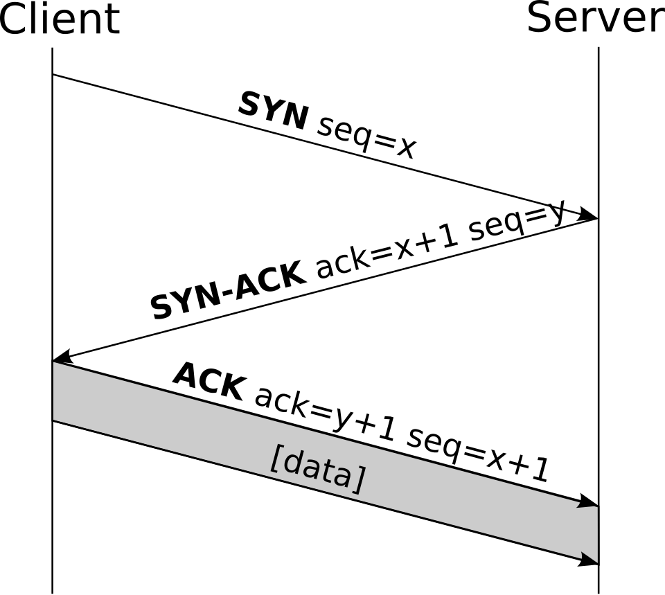 SYN, SYN-ACK, ACK process (Image: CC BY-SA 3.0, via Wikimedia Commons)
5. Configuring Network Interfaces in Linux
Linux uses commands like ip, ifconfig (legacy), and /etc/network/interfaces to configure interfaces.
5.1 Basic Commands
| Command | Description |
|---|---|
ip a or ifconfig |
Show all network interfaces and IPs. |
ip addr add 192.168.1.10/24 dev eth0 |
Assign an IP to eth0. |
ip route add default via 192.168.1.1 |
Set default gateway. |
ping 8.8.8.8 |
Test connectivity to Google’s DNS. |
traceroute google.com |
Trace the path to Google. |
Example: Configuring a Linux Server for a Web Host
# Assign IP and enable interface
sudo ip addr add 203.127.199.100/24 dev ens33
sudo ip link set ens33 up

# Set default gateway
sudo ip route add default via 203.127.199.1

# Test connectivity
ping 203.127.199.1
6. Troubleshooting Network Issues
Common issues and commands to diagnose them:
| Issue | Possible Cause | Diagnostic Command |
|---|---|---|
| No internet access | Wrong gateway or DNS | ping 8.8.8.8, nslookup google.com |
| Slow connection | Congestion or high latency | traceroute google.com, mtr |
| Devices on same network can’t ping each other | Incorrect subnet mask or ARP issue | arp -a, ipcalc |
| Router not forwarding traffic | ACL or firewall blocking | iptables -L, tcpdump |
Example: Fixing a Subnet Mismatch
- Problem: Two PCs on
192.168.1.0/24can’t ping each other. - Diagnosis:
PC1: ip a → 192.168.1.10/25 PC2: ip a → 192.168.1.200/25 - Solution: Both must be on the same subnet (e.g.,
/24). Change PC2’s subnet mask to255.255.255.0.
In the Real World
eSewa and Khalti (Payment Gateways)
- Idea Used: Load balancing and dynamic routing.
- How: During Diwali, millions of transactions hit eSewa’s servers. They use BGP for dynamic routing to distribute traffic across multiple data centers (e.g., Kathmandu, Pokhara). If one server fails, BGP reroutes traffic instantly.
Daraz (E-Commerce)
- Idea Used: Subnetting and VLSM.
- How: Daraz’s backend uses /24 subnets for different services (e.g.,
10.0.1.0/24for web servers,10.0.2.0/24for databases). VLSM ensures they don’t waste IPs on small departments (e.g., HR gets/28).
NTC’s Fiber Optic Backbone
- Idea Used: Mesh topology and OSPF.
- How: NTC’s national fiber network uses a partial mesh for redundancy. If a fiber link fails (e.g., Kathmandu-Pokhara), OSPF recalculates routes in <10 seconds, ensuring no downtime for Ncell or Internet users.
Exam Tip
- Subnetting is a high-weight topic: Always show your work step-by-step (e.g., "borrow 2 bits for 4 subnets").
- Compare static vs. dynamic routing: Know when to use each (e.g., static for home routers, dynamic for ISPs).
- TCP/IP layers: Memorize protocols by layer (e.g., HTTP is Application, ARP is Network Access).
- Real-world scenarios: Expect questions like:
- "A university has 5 departments. Design a subnet plan for 100, 50, 30, 20, and 10 hosts."
- "Explain how Pathao uses dynamic routing to handle rider locations."
- Commands: Know
ip,ping,traceroute, andnslookupoutputs. - Diagrams: Draw OSI/TCP/IP layers, subnetting examples, and topologies in exams. Label everything!
Based on the TU BITM syllabus for Networking and System Administration (IT271), unit 5.
Discussion
Loading…