Introduction to Cloud ComputingUnit 38 min read
Cloud Virtualization Technology – Hypervisors, VMs, Containers, and Management
Unit 3 of Introduction to Cloud Computing: covers virtualization fundamentals, hypervisor types, VM lifecycle, containerization, orchestration, and real‑world applications.
Key points
- Virtualization abstracts physical resources to create isolated virtual machines (VMs) or containers.
- Type‑1 (bare‑metal) hypervisors provide higher performance and security compared to Type‑2 (hosted) hypervisors.
- VM lifecycle includes creation, configuration, boot, snapshot, migration, and termination.
- Containers share the host kernel, offering faster startup and lower overhead than full VMs.
- Kubernetes orchestrates container workloads, enabling scalable, resilient cloud services.
Introduction to Cloud Virtualization
Virtualization is the abstraction of physical computing resources—CPU, memory, storage, and network—into logical units that can be independently managed and isolated. In cloud computing, virtualization is the foundation that allows multi‑tenant infrastructure, rapid provisioning, and elastic scaling.
Key Concepts
- Virtual Machine (VM): A software emulation of a complete computer system that runs a guest operating system (OS) on top of a hypervisor.
- Hypervisor (Virtual Machine Monitor, VMM): Software that creates, runs, and manages VMs by translating guest OS requests into host hardware operations.
- Container: A lightweight, OS‑level virtualization that packages an application and its dependencies into a single executable unit, sharing the host kernel.
- Orchestration: Automated management of container lifecycles, scaling, networking, and fault tolerance, typically via platforms like Kubernetes.
Hypervisor Types
| Feature | Type‑1 (Bare‑Metal) | Type‑2 (Hosted) |
|---|---|---|
| Deployment | Installed directly on physical hardware | Runs on a host OS |
| Performance | Near‑native, minimal overhead | Higher overhead due to host OS |
| Security | Strong isolation, fewer attack vectors | Dependent on host OS security |
| Use Cases | Enterprise data centers, cloud providers | Desktop virtualization, development environments |
flowchart TD
    A["Physical Server"] --> B["Type‑1 Hypervisor"]
    B --> C["VM1"]
    B --> D["VM2"]
    B --> E["VM3"]
    A --> F["Type‑2 Hypervisor"]
    F --> G["VM4"]
    F --> H["VM5"]
Figure 1: Hypervisor deployment models.How a Type‑1 Hypervisor Works
- Hardware Abstraction Layer (HAL): The hypervisor directly interfaces with CPU, memory, I/O devices.
- Virtual Machine Monitor (VMM): Intercepts privileged instructions from guest OS, translating them into host operations.
- Resource Scheduler: Allocates CPU cycles, memory pages, and I/O bandwidth to each VM.
- Device Emulation: Provides virtual devices (disk, NIC, GPU) to guests.
Virtual Machine Lifecycle – Worked Example
Consider a user launching a Windows Server VM on VMware ESXi.
| Step | Action | Hypervisor Response | Guest OS State |
|---|---|---|---|
| 1 | Create VM | ESXi creates a VM configuration file (.vmx) and allocates a virtual disk (.vmdk). | Not yet booted |
| 2 | Configure Resources | User sets 4 vCPU, 8 GB RAM, 100 GB disk. | Not yet booted |
| 3 | Boot | ESXi loads the VM’s virtual CPU, memory, and virtual disk into the host. The guest BIOS starts, loads the Windows kernel. | Booting |
| 4 | Snapshot | User takes a snapshot. ESXi records the VM’s memory state and disk changes. | Running |
| 5 | Live Migration | VM is moved to another ESXi host. ESXi streams memory pages while the VM remains online. | Running |
| 6 | Terminate | VM is powered off; resources are released. | Off |
Figure 2: VM lifecycle stages in a hypervisor.
Virtual Machine Architecture
A VM consists of:
- Virtual CPU (vCPU): Logical CPU cores mapped to physical cores.
- Virtual Memory: Guest OS sees a contiguous memory space; hypervisor maps pages to host RAM.
- Virtual Disk: File or block device that represents the VM’s storage.
- Virtual NIC: Emulated network interface connected to a virtual switch.
classDiagram
    class Hypervisor {
        +allocateResources()
        +scheduleCPU()
        +translateIO()
    }
    class VM {
        +vCPU
        +vMemory
        +vDisk
        +vNIC
    }
    Hypervisor --> VM : manages
Storage Virtualization
- Virtual Disk Formats: VMDK (VMware), QCOW2 (QEMU/KVM), VHDX (Hyper‑V).
- Thin Provisioning: Disk space allocated on demand, saving physical storage.
- Snapshots & Clones: Point‑in‑time copies for backup or rapid deployment.
Network Virtualization
- Virtual Switch (vSwitch): Connects VMs to each other and to the physical network.
- Virtual NIC (vNIC): Each VM has one or more vNICs, each with a MAC address.
- Overlay Networks: VXLAN, NVGRE encapsulate VM traffic over physical infrastructure.
Containerization – Docker & Images
Containers differ from VMs in that they share the host kernel and use OS‑level isolation (cgroups, namespaces).
Docker Image Layers
A Docker image is built from a series of layers, each representing a filesystem change.
sequenceDiagram
    participant User
    participant Docker
    User->>Docker: docker build
    Docker->>Docker: Layer 1 (FROM base)
    Docker->>Docker: Layer 2 (RUN apt‑get install)
    Docker->>Docker: Layer 3 (COPY app)
    Docker->>Docker: Image complete
Figure 3: Docker image build process.Container vs VM Comparison
| Feature | VM | Container |
|---|---|---|
| Kernel | Separate per VM | Shared with host |
| Startup Time | Minutes | Seconds |
| Overhead | Disk, memory, CPU | Minimal |
| Isolation | Strong (hardware level) | Process‑level |
| Use Cases | Legacy apps, multi‑OS | Microservices, CI/CD |
Orchestration – Kubernetes Architecture
graph TD
    A["Client"] --> B["API Server"]
    B --> C["Controller Manager"]
    B --> D["Scheduler"]
    B --> E["etcd"]
    C --> F["Replication Controller"]
    D --> G["Node"]
    G --> H["Container Runtime"]
    G --> I["Kubelet"]
    G --> J["Kube Proxy"]
    subgraph Cluster
        G
    end
Figure 4: Core components of a Kubernetes cluster.Kubernetes manages container workloads across a cluster of nodes, providing scaling, self‑healing, and service discovery.
Advantages & Disadvantages
| Aspect | Virtualization | Containerization |
|---|---|---|
| Performance | Slight overhead due to hypervisor | Near‑native |
| Isolation | Strong, hardware‑level | Process‑level |
| Portability | Requires hypervisor support | OS‑level, easier |
| Resource Utilization | Higher due to full OS | Efficient |
| Management | Complex VM lifecycle | Simplified via orchestration |
Applications in Cloud and Edge
- Public Clouds: AWS EC2 (VMs), Google Compute Engine (VMs), Azure VMs.
- Private Clouds: OpenStack (VMs + containers), VMware vSphere.
- Edge Computing: Virtualized network functions (VNFs) on 5G base stations.
- DevOps: Docker for CI pipelines, Kubernetes for production deployments.
In the real world
- eSewa (Digital Wallet) – Uses Docker containers to host microservices (payment processing, user authentication). Each service runs in its own container, sharing the host kernel, enabling rapid scaling during peak transaction periods.
- Pathao (Logistics & Ride‑Sharing) – Deploys a Kubernetes cluster on Google Cloud to manage its delivery‑tracking microservices. Autoscaling pods handle fluctuating demand during festivals.
- Ncell (Telecom) – Virtualizes network functions (e.g., BSS/OSS) using VMware ESXi. Virtual routers and firewalls run as VMs, allowing rapid deployment of new services without physical hardware changes.
Worked Example – Daraz Order Queue
Daraz’s order processing system uses a Kubernetes deployment with 3 replicas of the order‑processor pod. Each pod consumes messages from a RabbitMQ queue. When the queue length exceeds 200 messages, the Horizontal Pod Autoscaler (HPA) scales replicas to 6, reducing average processing time from 5 s to 1 s. The system’s resilience is ensured by Kubernetes’ self‑healing: if a pod crashes, it is automatically restarted.
Exam tip
- Understand the difference between Type‑1 and Type‑2 hypervisors – be able to list advantages and typical use cases.
- Explain the VM lifecycle – especially snapshotting and live migration.
- Compare VMs and containers – focus on isolation, performance, and use‑case suitability.
- Describe Kubernetes architecture – know the role of API server, scheduler, controller manager, etc.
- Be ready to draw a simple hypervisor or Kubernetes diagram – use mermaid or figure blocks as shown.
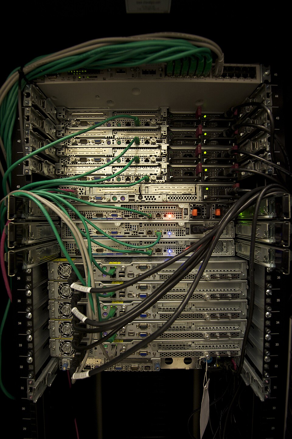 Typical enterprise server rack used in data centers (Image: Abigor, CC BY-SA 3.0, via Wikimedia Commons)
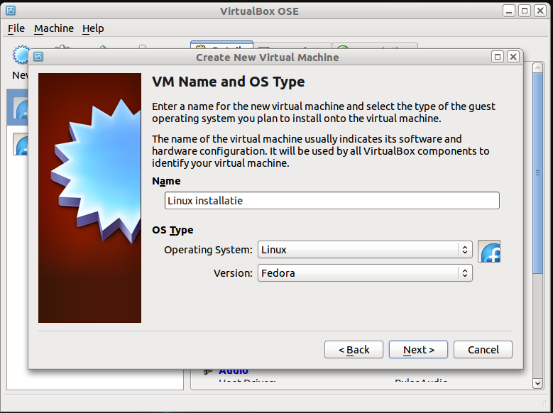 Illustration of a virtual machine running inside a hypervisor (Image: Zippie666 at Dutch Wikibooks, GPL, via Wikimedia Commons)
Based on the TU BSc CSIT syllabus for Introduction to Cloud Computing, unit 3.
Discussion
Loading…