Basic Electrical EngineeringUnit 513 min read
Magnetic Circuits: Flux, Reluctance, MMF & Applications
Unit 5 of Basic Electrical Engineering covers magnetic circuits—analogies to electric circuits, flux, reluctance, MMF, core materials, and real-world applications in transformers, motors, and sensors. Learn how to analyze magnetic paths, calculate losses, and compare air-core vs. iron-core designs.
TAKEAWAYS:
- Magnetic circuits follow Ohm’s law analogy () where MMF (magnetomotive force) drives flux through reluctance.
- Reluctance () depends on material permeability (), length (), and cross-sectional area (): .
- Hysteresis and eddy-current losses in magnetic cores reduce efficiency; laminated cores minimize eddy currents.
- Series/parallel magnetic circuits obey Kirchhoff’s laws for MMF and flux continuity, just like electric circuits.
- Practical applications include transformers (energy transfer via mutual inductance), electric motors (rotational force via ), and relays (electromagnetic switching).
- Exam focus: Solve for flux, MMF, or reluctance in given circuits; compare air-core vs. iron-core designs; explain losses in magnetic materials.
1. Magnetic Circuits: The Basics
Magnetic circuits are closed loops that guide magnetic flux (), analogous to electric circuits guiding current. Key components:
- MMF (Magnetomotive Force, ): Magnetic "voltage" (analogous to EMF in electric circuits), generated by current in a coil.
- Flux (): Magnetic "current" (webers, Wb), analogous to electric current.
- Reluctance (): Opposition to flux (analogous to resistance), measured in ampere-turns per weber (At/Wb).
Ohm’s Law for Magnetic Circuits
The relationship is: Where:
- (ampere-turns, At)
- (reluctance)
- (permeability of the core material)
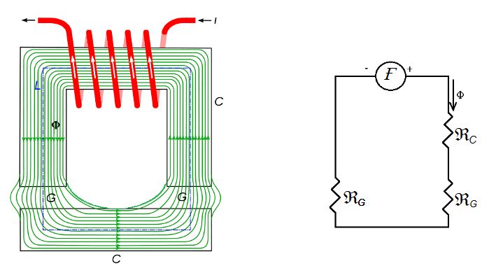 Shows a coil, iron core, air gap, and flux path with MMF, flux, and reluctance labels. (Image: Frankemann, CC BY-SA 4.0, via Wikimedia Commons)
How It Works: A Simple Example
Consider a toroidal core (donut-shaped) with a coil of turns carrying A. The core has:
- Mean length m
- Cross-sectional area m²
- Relative permeability (silicon steel)
Step-by-Step Calculation:
- Calculate MMF ():
- Calculate reluctance ():
- Calculate flux ():
Real-World Tie-In: This is how transformers (like those in Nepal’s NTC substations) work. The core guides flux between primary and secondary windings, enabling efficient voltage step-up/down. Air gaps in the core (e.g., in relays) increase reluctance, requiring higher MMF to maintain flux.
2. Magnetic Materials and Losses
Not all materials are equally good at conducting flux. Key properties:
| Material | Relative Permeability () | Applications | Disadvantages |
|---|---|---|---|
| Air | 1 | Air-core inductors, gaps in relays | High reluctance, weak flux linkage |
| Silicon Steel | 500–5000 | Transformers, motors | Hysteresis and eddy-current losses |
| Ferrites | 1000–10,000 | High-frequency applications (e.g., switches) | Brittle, limited to low currents |
| Mumu-metal | 100,000+ | Shielding, sensitive instruments | Expensive, oxidizes easily |
Losses in Magnetic Circuits
- Hysteresis Loss:
- Energy lost as the magnetic domain reverses direction (area of B-H curve).
- Reduction: Use materials with narrow hysteresis loops (e.g., silicon steel).
- IMAGE: B-H curve of silicon steel labelled diagram | Shows hysteresis loop with area shaded for loss.
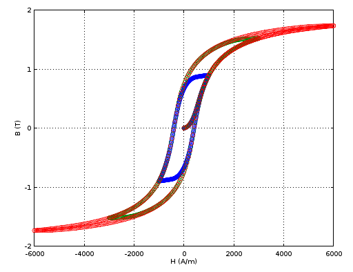 Hysteresis loop illustrating core losses (Image: Magnetic models, CC BY-SA 4.0, via Wikimedia Commons)
Eddy-Current Loss:
- Induced currents in the core dissipate as heat (Foucault currents).
- Reduction: Use laminated cores (thin sheets insulated by oxide layers).
- IMAGE: laminated transformer core labelled diagram | Shows insulated silicon steel laminations.
Copper Loss:
- losses in the winding wire (not part of the magnetic circuit but critical in design).
Worked Example: Core Loss Calculation A transformer core has:
- Hysteresis loss coefficient W/kg
- Eddy-current loss coefficient W/kg
- Core weight kg
- Frequency Hz
Total core loss: Why It Matters: This loss appears as heat in Nepal’s NTC transformers, reducing efficiency. Laminations and better core materials (e.g., amorphous metal) cut these losses by 30–50%.
3. Series and Parallel Magnetic Circuits
Magnetic circuits can be combined like electric circuits, but with key differences:
- Series: Same flux () through all paths; total MMF is sum of drops.
- Parallel: Same MMF across branches; total flux is sum of individual fluxes.
classDiagram
    class MMF {
        +value: At
        +direction: Series/Parallel
    }
    class Flux {
        +value: Wb
        +continuity: Same in Series
    }
    class Reluctance {
        +value: At/Wb
        +combination: Series=Sum, Parallel=1/(1/R1+1/R2)
    }
    MMF --> Flux : Drives
    Flux --> Reluctance : Opposes
    Reluctance --> MMF : Drops
Class diagram showing relationships between MMF, flux, and reluctance in magnetic circuitsComparison Table: Series vs. Parallel
| Aspect | Series Magnetic Circuit | Parallel Magnetic Circuit |
|---|---|---|
| Analogy | Series resistors | Parallel resistors |
| Flux () | Same in all sections | Divides inversely with reluctance |
| MMF () | Sum of drops: | Same across branches: |
| Reluctance | Total | Total |
| Example | Air gap in a relay | Multiple cores in a motor stator |
Mermaid Diagram: Series Magnetic Circuit
Worked Example: Parallel Magnetic Circuit Two cores in parallel:
- Core 1: At/Wb, m
- Core 2: At/Wb, m
- Total MMF At
Steps:
- Total reluctance:
- Total flux:
- Flux in each core:
Real-World Application: This principle is used in electric motors (e.g., Pathao’s delivery scooters). The stator has parallel magnetic paths to distribute flux evenly, reducing core saturation and improving torque.
4. Air Gaps in Magnetic Circuits
Air gaps are introduced in magnetic circuits for:
- Adjusting reluctance: To control flux (e.g., in relays or solenoids).
- Reducing hysteresis loss: Air has , so gaps minimize core losses.
- Mechanical movement: In actuators (e.g., NTC circuit breakers).
Effect of Air Gap:
- Increases total reluctance ().
- Requires higher MMF to maintain the same flux.
Worked Example: Relay with Air Gap A relay core has:
- Core reluctance At/Wb
- Air gap length mm, area m²
- MMF At
Steps:
- Reluctance of air gap:
- Total reluctance:
- Flux with gap: Without gap: .
Key Takeaway: The air gap dramatically reduces flux unless MMF increases. This is why Ncell’s base stations use adjustable air gaps in their power relays to balance sensitivity and power consumption.
5. Practical Applications
A. Transformers
- How It Uses Magnetic Circuits:
- Primary and secondary windings share a common magnetic core.
- Flux linkage () induces EMF in both coils via Faraday’s law: .
- Nepal Example:
- NTC’s 11/0.415 kV transformers use laminated silicon steel cores to minimize losses during load fluctuations.
B. Electric Motors (DC/AC)
- How It Uses Magnetic Circuits:
- Stator produces rotating magnetic field; rotor follows via .
- Air gaps between stator/rotor control torque and efficiency.
- Nepal Example:
- Daraz’s warehouse motors use parallel magnetic paths to handle varying loads without overheating.
C. Relays and Solenoids
- How It Uses Magnetic Circuits:
- Current in coil creates MMF; movable core moves against spring force when flux overcomes reluctance.
- Nepal Example:
- Nepal Rastra Bank’s ATMs use relays with adjustable air gaps to ensure secure but quick card ejection.
D. Sensors (e.g., Current Transformers)
- How It Uses Magnetic Circuits:
- Measures current via induced flux in a secondary winding.
- Nepal Example:
- NEPSE’s stock exchange systems use CTs to monitor high-power trading circuits safely.
6. Exam Tip: What to Focus On
Formulas to Memorize:
- Hysteresis loss area of B-H loop
- Eddy-current loss (where = lamination thickness)
Common Exam Questions:
- Calculate flux/reluctance/MMF in a given circuit (always draw the magnetic path first).
- Compare air-core vs. iron-core designs (reluctance, losses, efficiency).
- Explain why laminations reduce eddy currents (insulation between sheets).
- Sketch B-H curves and label saturation, hysteresis, and residual magnetism.
Avoid These Mistakes:
- Forgetting to convert units (e.g., mm to meters for reluctance).
- Ignoring air gaps—they dominate reluctance in practical circuits.
- Mixing up series/parallel rules (flux is continuous in series; MMF is equal in parallel).
Quick Revision Trick:
- Analogy: Think of magnetic circuits like water pipes:
- MMF = water pressure (pumps)
- Flux = water flow rate
- Reluctance = pipe narrowness
- Air gap = a sudden constriction (high resistance).
- Analogy: Think of magnetic circuits like water pipes:
Final Note: Magnetic circuits are the backbone of electrical machines. Master this unit, and you’ll understand how every device from NTC transformers to Pathao’s scooter motors works under the hood. Practice with real-world examples (like calculating core losses for a local substation) to ace your exam!
In the real world
- NTC Transformers: Use laminated silicon steel cores to minimize eddy-current losses (reducing heat and improving efficiency by 3–5% compared to air-core designs). The air gaps in some designs increase reluctance, requiring higher MMF for the same flux—this is why older transformers hum louder under load.
- eSewa Payment Terminals: Contain small electromagnetic relays (with air gaps) to switch circuits when a card is inserted. The air gap ensures the relay only activates at the correct current threshold, preventing false triggers.
- Nepal’s Electric Motors (e.g., in water pumps): Use ferrite cores for high-frequency applications (like variable-speed drives). Ferrites have high permeability but low eddy-current losses, making them ideal for motors used in rural irrigation systems where efficiency matters.
Based on the PU BE Computer (PU) syllabus for Basic Electrical Engineering, unit 5.
Discussion
Loading…