Basic Electrical EngineeringUnit 413 min read
Capacitance & Inductance: Storage, Energy & Dynamic Circuits
Unit 4 of Basic Electrical Engineering covers capacitors and inductors—their behavior in DC/AC circuits, energy storage, resonance, and real-world applications in power systems, electronics, and communication. Learn definitions, formulas, transient responses, and how they interact with resistors in RLC circuits.
TAKEAWAYS
- Capacitors store energy in electric fields (voltage-dependent) and block DC but allow AC; inductors store energy in magnetic fields (current-dependent) and block AC but allow DC.
- Time constants (τ) determine how fast capacitors charge/discharge or inductors reach steady state: τ = RC for capacitors, τ = L/R for inductors.
- Resonance in RLC circuits occurs when X_L = X_C, maximizing current (series) or voltage (parallel) at the resonant frequency f₀ = 1/(2π√(LC)).
- Energy equations: Capacitors store ½CV², inductors store ½LI²; both release energy when discharged.
- Applications: Capacitors filter noise (power supplies), couple signals (amplifiers); inductors block high-frequency noise (chokes), store energy (switching regulators).
- Exam focus: Sketch transient responses, derive time constants, analyze series/parallel RLC resonance, and solve energy/voltage/current relationships.
1. Capacitors: The Electric Field Energy Banks
1.1 Definition & Basic Behavior
A capacitor is a passive two-terminal device that stores electrical energy in an electric field when charged. It consists of two conductive plates separated by a dielectric (insulating material like air, paper, or ceramic).
Key properties:
- Capacitance (C): Ability to store charge per unit voltage, measured in farads (F).
- Voltage-current relationship:
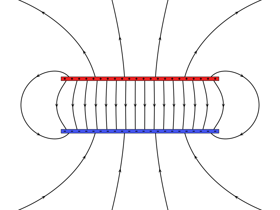 Shows plate separation, dielectric, and electric field lines between plates. (Image: Geek3, CC BY-SA 4.0, via Wikimedia Commons)
1.2 Types of Capacitors & Their Symbols
| Type | Symbol | Dielectric | Applications |
|---|---|---|---|
| Ceramic | ![Ceramic] | Ceramic material | High-frequency circuits, decoupling |
| Electrolytic | ![Electrolytic] | Electrolyte gel | Power supplies, audio filters |
| Film | ![Film] | Plastic film | Precision timing circuits |
| Variable | ![Variable] | Air or mechanical | Tuning circuits (e.g., radios) |
1.3 Capacitors in DC Circuits: Charging & Discharging
When connected to a DC source, capacitors charge/discharge exponentially with a time constant τ = RC.
Charging Process:
- At t = 0⁺, voltage across capacitor = 0, current = I₀ = V/R (max).
- As capacitor charges, voltage rises, current decays.
- At t = τ = RC, voltage reaches ~63.2% of V₀, current drops to ~36.8% of I₀.
- At t = 5τ, capacitor is fully charged (99.3% of V₀).
Discharging Process:
- At t = 0⁺, voltage = V₀, current = I₀ = V₀/R.
- Voltage decays exponentially; current follows.
- At t = τ, voltage = ~36.8% of V₀.
Worked Example: Charging a Capacitor in a Flashlight A 1000 µF capacitor is charged by a 9V battery through a 50 Ω resistor.
- Time constant (τ): .
- Voltage after 0.1 s: .
- Current at t = 0.025 s: .
1.4 Capacitors in AC Circuits: Reactance & Phase Shift
In AC circuits, capacitors introduce capacitive reactance (X_C), which opposes changes in voltage:
- X_C decreases with frequency: At high frequencies, capacitors act like short circuits; at low frequencies, they act like open circuits.
- Phase relationship: Current leads voltage by 90° in a purely capacitive circuit.
Worked Example: Capacitor in a Smartphone Power Supply A 10 µF capacitor is used to filter noise in a 50 Hz power supply.
- X_C: .
- If connected to a 12V AC source, the rms current is .
1.5 Energy Storage in Capacitors
Energy stored in a capacitor: Example: A 100 µF capacitor charged to 10V stores:
2. Inductors: The Magnetic Field Energy Banks
2.1 Definition & Basic Behavior
An inductor is a passive two-terminal device that stores energy in a magnetic field when current flows through it. It consists of a coil of wire, often wound around a core (air, iron, or ferrite).
Key properties:
- Inductance (L): Opposition to changes in current, measured in henries (H).
- Voltage-current relationship:
2.2 Types of Inductors & Their Symbols
| Type | Symbol | Core Material | Applications |
|---|---|---|---|
| Air-core | ![Air-core] | Air | RF circuits, high-frequency tuning |
| Iron-core | ![Iron-core] | Ferromagnetic | Power transformers, motors |
| Variable | ![Variable] | Adjustable core | Radio tuning, oscillators |
2.3 Inductors in DC Circuits: Growth & Decay of Current
When connected to DC, inductors resist changes in current with a time constant τ = L/R.
Current Growth (Charging):
- At t = 0⁺, current = 0, voltage = V₀ (max).
- Current rises exponentially; voltage decays.
- At t = τ = L/R, current = ~63.2% of I₀, voltage = ~36.8% of V₀.
- At t = 5τ, current reaches ~99.3% of I₀.
Current Decay (Discharging):
- At t = 0⁺, current = I₀, voltage = L(I₀/R).
- Current decays exponentially; voltage follows.
Worked Example: Inductor in a Motor Starter A 100 mH inductor with 10 Ω resistance is connected to a 12V DC supply.
- Time constant (τ): .
- Current after 0.02 s: .
2.4 Inductors in AC Circuits: Reactance & Phase Shift
In AC circuits, inductors introduce inductive reactance (X_L), which opposes changes in current:
- X_L increases with frequency: At high frequencies, inductors act like open circuits; at low frequencies, they act like short circuits.
- Phase relationship: Voltage leads current by 90° in a purely inductive circuit.
Worked Example: Inductor in a Washing Machine Motor A 50 mH inductor is used in a 60 Hz motor.
- X_L: .
- If connected to a 230V AC source, the rms current is .
2.5 Energy Storage in Inductors
Energy stored in an inductor: Example: A 200 mH inductor carrying 5A stores:
3. RLC Circuits: The Dance of Resistance, Inductance & Capacitance
When resistors (R), inductors (L), and capacitors (C) are combined, they form RLC circuits, which exhibit resonance, transient responses, and frequency-dependent behavior.
3.1 Series RLC Circuits
In a series RLC circuit, the total impedance (Z) is:
- Resonance occurs when X_L = X_C, i.e.,
- At resonance:
- Impedance is minimum (Z = R).
- Current is maximum (I = V/R).
- Phase angle is zero (voltage and current in phase).
Worked Example: Tuning a Radio (AM Band) An AM radio tuner uses a series RLC circuit with L = 250 µH and C = variable.
- To tune to 1 MHz (f₀ = 1 × 10⁶ Hz), the required capacitance is:
3.2 Parallel RLC Circuits
In a parallel RLC circuit, the total admittance (Y) is:
- Resonance occurs when X_L = X_C, same as series:
- At resonance:
- Admittance is minimum (Y = 1/R).
- Impedance is maximum (Z = R).
- Voltage is maximum across the parallel branch.
Worked Example: Voltage Stabilization in Power Supplies A parallel LC filter is used to stabilize voltage in a 50 Hz power supply.
- If L = 100 mH and C = 10 µF, the resonant frequency is:
- This filters out 50 Hz noise, providing a smoother DC output.
3.3 Quality Factor (Q) & Bandwidth
The quality factor (Q) measures how selective a resonant circuit is:
- High Q: Narrow bandwidth, sharp resonance (used in radios).
- Low Q: Wide bandwidth, dull resonance (used in filters).
Worked Example: Q Factor of a Tuning Circuit A series RLC circuit has R = 10 Ω, L = 1 mH, C = 1 µF.
- Resonant frequency:
- Q factor:
- Bandwidth (Δf):
## In the Real World
Khalti & eSewa (Digital Payments)
- Capacitors are used in power supply filtering to smooth out voltage fluctuations from the grid, ensuring stable operation of payment gateways.
- Inductors act as chokes in switch-mode power supplies to block high-frequency noise, preventing data corruption in transactions.
Ncell & NTC (Telecom & Power Grid)
- RLC filters in mobile base stations (Ncell) tune specific frequencies for signal transmission, improving call quality.
- Power factor correction capacitors in Nepal’s grid (NTC) compensate for inductive loads (motors, transformers), reducing energy loss.
Pathao & Daraz (Logistics & E-Commerce)
- Inductive sensors in automated warehouses (Daraz) detect package positions on conveyor belts for sorting.
- Capacitive touchscreens in Pathao driver apps rely on capacitance changes to register user input.
## Exam Tip
Memorize key formulas:
- Capacitive reactance:
- Inductive reactance:
- Resonant frequency:
- Energy in capacitor/inductor: or
Sketch transient responses:
- Always draw exponential curves for charging/discharging capacitors/inductors, labeling τ = RC or τ = L/R.
Analyze resonance:
- For series RLC, current peaks at ; for parallel RLC, voltage peaks at .
- Calculate Q factor and bandwidth when asked about selectivity.
Real-world applications:
- Relate capacitors to filtering (e.g., power supplies, audio crossovers).
- Relate inductors to energy storage (e.g., flyback converters in chargers) or signal tuning (e.g., radios).
Common pitfalls:
- Don’t confuse X_L and X_C: increases with frequency; decreases.
- Phase angles: Current leads voltage in capacitors, lags in inductors.
- Units: Always check if C is in farads or µF, L in henries or mH.
## Practice Questions (Exam-Style)
A 5 µF capacitor is charged to 20V and then connected across a 1 kΩ resistor. Find:
- The time constant (τ).
- The voltage across the capacitor after 0.01 s.
- The energy stored initially.
An RLC series circuit has R = 20 Ω, L = 100 mH, C = 10 µF, and is driven by a 10V, 50 Hz source. Calculate:
- The inductive and capacitive reactances.
- The total impedance and phase angle.
- The resonant frequency of the circuit.
Explain why capacitors are used in parallel with loads in power factor correction, while inductors are avoided.
## Summary Table: Capacitors vs. Inductors
| Property | Capacitor | Inductor |
|---|---|---|
| Energy Storage | Electric field () | Magnetic field () |
| Opposition to | Change in voltage | Change in current |
| Reactance (X) | ||
| Phase Relationship | Current leads voltage by 90° | Voltage leads current by 90° |
| DC Behavior | Acts as open circuit (blocks DC) | Acts as short circuit (allows DC) |
| AC Behavior | Acts as short circuit at high f | Acts as open circuit at high f |
| Applications | Filtering, coupling, timing | Chokes, energy storage, tuning |
Based on the PU BE Computer (PU) syllabus for Basic Electrical Engineering, unit 4.
Discussion
Loading…