Basic Electrical EngineeringUnit 311 min read
Network Theorems: Nodal, Mesh, Superposition, Thevenin, Norton & Star-Delta
Unit 3 of Basic Electrical Engineering covers Network Theorems—key analytical tools for simplifying and solving complex DC circuits. Learn Nodal Analysis, Mesh Analysis, Superposition Theorem, Thevenin’s Theorem, Norton’s Theorem, and Star-Delta (Y-Δ) Transformation, with real-world applications in power systems, elect
TAKEAWAYS:
- Nodal Analysis simplifies circuits by writing KCL equations at nodes, reducing unknowns to n-1 for n nodes.
- Mesh Analysis uses KVL around loops, ideal for planar circuits with independent current sources.
- Superposition Theorem breaks multi-source circuits into single-source cases, valid only for linear circuits.
- Thevenin’s Theorem replaces a complex network with a single voltage source + series resistance, simplifying analysis.
- Norton’s Theorem does the same using a current source + parallel resistance; both are equivalent via source conversion.
- Star-Delta (Y-Δ) Transformation converts 3-terminal networks between star (Y) and delta (Δ) forms, crucial for 3-phase systems.
1. Introduction to Network Theorems
Network theorems are mathematical tools that simplify complex electrical circuits into manageable forms. They are based on Kirchhoff’s Laws (KCL, KVL) and Ohm’s Law, allowing engineers to analyze circuits without solving every element individually.
Why Use Network Theorems?
- Reduce complexity of large circuits.
- Simplify analysis by breaking circuits into smaller, solvable parts.
- Standardize solutions for repeated sub-circuits (e.g., amplifiers, filters).
- Optimize design by predicting behavior before building prototypes.
2. Nodal Analysis (Node Voltage Method)
Nodal analysis is a systematic method to find voltages at all nodes in a circuit relative to a reference node (ground).
Key Steps:
- Identify nodes: Choose a reference node (ground) and label others.
- Apply KCL: Sum currents leaving each node = 0.
- Express currents in terms of voltages: Use for resistors.
- Solve equations: Use substitution or matrix methods.
Example: Solving a Circuit Using Nodal Analysis
Circuit: 3 nodes (V₁, V₂, V₃), reference ground, with resistors and current sources. Given:
- (current source between V₁ and ground)
- , ,
- Voltage source between V₂ and V₃.
Step-by-Step Solution:
- Write KCL at V₁:
- Write KCL at V₂:
- Write KCL at V₃ (with due to voltage source):
- Solve the system:
- Substitute into the second equation.
- Solve for and .
Answer:
3. Mesh Analysis (Loop Current Method)
Mesh analysis is used for planar circuits (circuits that can be drawn on a plane without crossing lines). It uses loop currents and KVL.
Key Steps:
- Identify meshes: Assign a current to each independent loop.
- Apply KVL: Sum voltage drops = 0 around each loop.
- Solve for mesh currents: Use substitution or matrix methods.
Example: Solving a Circuit Using Mesh Analysis
Circuit: 2 meshes with resistors and a voltage source. Given:
- , ,
- between mesh 1 and 2.
Step-by-Step Solution:
- Define mesh currents (mesh 1) and (mesh 2).
- Write KVL for Mesh 1:
- Write KVL for Mesh 2:
- Solve the system:
- Simplify equations:
- Solve using determinants or substitution.
Answer:
4. Superposition Theorem
The Superposition Theorem states that in a linear circuit with multiple independent sources, the response (voltage/current) in any branch is the algebraic sum of responses caused by each source acting alone.
Steps to Apply Superposition:
- Turn off all but one source:
- Replace voltage sources with short circuits.
- Replace current sources with open circuits.
- Calculate response (voltage or current) for that source alone.
- Repeat for all sources.
- Sum responses algebraically.
Example: Applying Superposition
Circuit: 2 sources (12V and 3A), resistors , . Find: Current through .
Step-by-Step Solution:
- Turn off 3A source (open circuit), keep 12V:
- (through ).
- Turn off 12V source (short circuit), keep 3A:
- Current divides: (through ).
- Sum responses:
5. Thevenin’s and Norton’s Theorems
These theorems simplify complex networks into equivalent circuits with a single source and impedance.
Thevenin’s Theorem
- Any linear bilateral network can be replaced by:
- A voltage source in series with a resistance .
- Steps:
- Find : Open-circuit voltage across terminals.
- Find : Resistance seen from terminals with all sources turned off.
Norton’s Theorem
- Any network can be replaced by:
- A current source in parallel with a resistance .
- Equivalence: , .
Example: Thevenin Equivalent of a Circuit
Circuit: 12V source, , , load resistor . Find: Thevenin equivalent seen from .
Step-by-Step Solution:
- Find :
- Open , voltage across terminals = .
- Find :
- Turn off 12V source (short circuit), .
- Thevenin equivalent:
- , .
Norton Equivalent:
- .
- .
6. Star-Delta (Y-Δ) Transformation
Used to convert between star (Y) and delta (Δ) connected networks, simplifying analysis.
Formulas:
| Star to Delta | Delta to Star |
|---|---|
Example: Converting Star to Delta
Given: Star resistors , , . Find: Equivalent Delta resistors.
Solution:
In the Real World
- eSewa (Nepal):
- Uses Thevenin/Norton equivalents to model power distribution networks for billing and load balancing.
- Example: When calculating voltage drops in long transmission lines, engineers use Thevenin equivalents to simplify analysis.
Ncell (Nepal):
- Mesh analysis is used in base station design to optimize antenna placement and minimize interference.
- Example: Engineers model signal paths between towers as meshes to ensure coverage overlap without dead zones.
Daraz (Nepal):
- Superposition Theorem helps in load balancing for their server farms.
- Example: If Daraz’s website has multiple data centers, traffic is distributed using superposition principles to ensure no single server is overwhelmed.
NTC (Nepal):
- Star-Delta transformations are used in 3-phase motor control for voltage regulation.
- Example: When starting a large industrial motor, NTC technicians use Y-Δ starters to limit inrush current.
Google (Global):
- Nodal analysis is used in chip design (e.g., Google’s data center servers) to model power distribution networks on silicon.
- Example: Engineers simulate voltage drops in CPU power delivery to prevent overheating.
Visuals
1. Nodal Analysis Example Circuit
 A circuit with 3 nodes, resistors, and current sources for nodal analysis. (Image: Petteri Aimonen, Public domain, via Wikimedia Commons)
2. Mesh Analysis Example Circuit
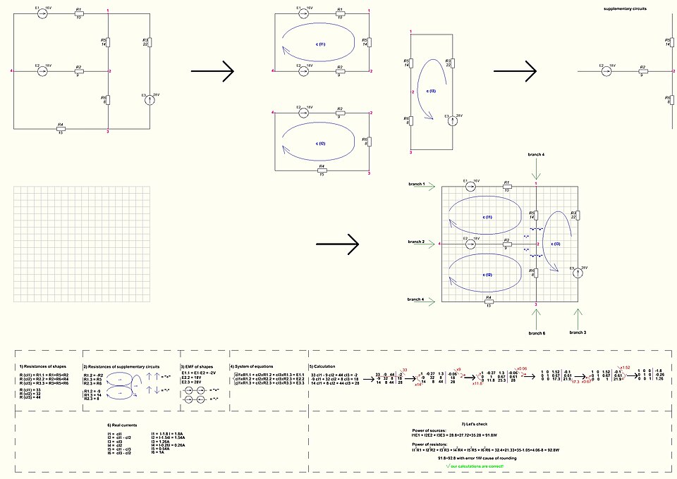 A planar circuit with 2 meshes, resistors, and a voltage source. (Image: Dmitry G, CC BY-SA 3.0, via Wikimedia Commons)
3. Thevenin Equivalent Circuit
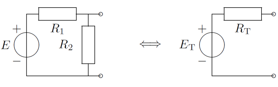 A complex network replaced by a voltage source and series resistor. (Image: Vesa Linja-aho, CC0, via Wikimedia Commons)
4. Star-Delta Transformation
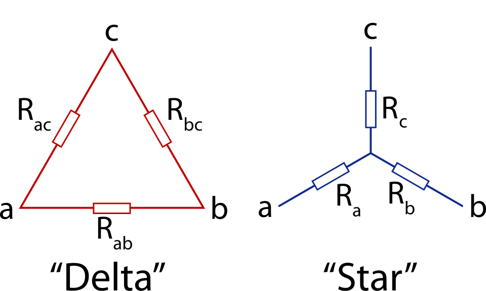 Star (Y) and Delta (Δ) connected resistors with equivalent values. (Image: jjbeard, Public domain, via Wikimedia Commons)
5. Superposition Theorem Example
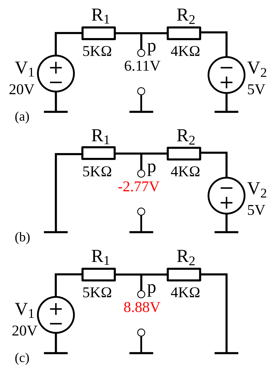 A circuit with multiple sources, showing individual responses. (Image: SteveZodiac, CC BY-SA 3.0, via Wikimedia Commons)
Exam Tip
For Nodal/Mesh Analysis:
- Always label nodes/meshes clearly.
- Write KCL/KVL equations systematically (avoid sign errors).
- Check units (volts, amps, ohms).
For Superposition:
- Turn off sources correctly (short voltage, open current).
- Sum responses algebraically (watch polarities).
For Thevenin/Norton:
- Memorize steps: Find , then .
- Verify equivalence by converting between Thevenin and Norton.
For Star-Delta:
- Use the formulas correctly (avoid mixing up ).
- Practice conversions in both directions.
Common Mistakes:
- Forgetting to ground the reference node in nodal analysis.
- Misapplying KVL (ignoring polarity).
- Incorrect source conversion in Thevenin/Norton.
Practice Questions (PU-Style)
- Using nodal analysis, find in the circuit below (given: , , , ).
- Apply mesh analysis to find currents in a 3-mesh circuit with , , , .
- Find the Thevenin equivalent of a network with , , , seen from two terminals.
- Convert a star network (, , ) to delta.
- Use superposition to find the voltage across in a circuit with , , and resistors , .
Based on the PU BE Computer (PU) syllabus for Basic Electrical Engineering, unit 3.
Discussion
Loading…