InstrumentationUnit 811 min read
Analog-Digital Conversion: ADCs, DACs, Sampling, Quantization & Error Analysis
Unit 8 of Instrumentation covers the core principles of converting real-world analog signals into digital data and vice versa, including sampling theory, quantization, ADC/DAC architectures (SAR, Flash, Delta-Sigma), error sources (aliasing, quantization noise), and real-world applications in data acquisition systems a
TAKEAWAYS:
- Analog-to-digital conversion (ADC) transforms continuous signals into discrete digital values via sampling and quantization, governed by the Nyquist theorem ().
- Digital-to-analog conversion (DAC) reconstructs analog signals from digital data, with resolution and linearity critical for accuracy.
- ADC architectures (Flash, SAR, Delta-Sigma) differ in speed, resolution, and power consumption, each suited for specific applications (e.g., audio, industrial sensors).
- Quantization error and aliasing introduce inaccuracies; anti-aliasing filters and oversampling mitigate these issues.
- Real-world systems (e.g., eSewa’s transaction logging, Ncell’s signal processing) rely on ADCs/DACs for data integrity and communication.
- Exam focus: Derive sampling rate requirements, compare ADC types, and analyze errors in signal reconstruction.
1. Analog-to-Digital Conversion (ADC): Fundamentals
ADC converts a continuous-time, continuous-amplitude analog signal into a discrete-time, discrete-amplitude digital signal. The process involves three key steps:
- Sampling: Capturing the analog signal at discrete intervals.
- Quantization: Mapping sampled values to finite digital levels.
- Encoding: Assigning binary codes to quantized levels.
1.1 Sampling Theorem (Nyquist-Shannon Sampling Theorem)
The sampling rate () must satisfy: where is the highest frequency component of the analog signal.
- Violation: Aliasing occurs, distorting the reconstructed signal.
- Example: If a sensor measures temperature variations up to 10 Hz, the sampling rate must be ≥20 Hz.
1.2 Quantization and Quantization Error
- Quantization: Assigning sampled values to the nearest discrete level.
- Quantization Error (): where is the sampled value and is the quantized level.
- Error Reduction: Increasing the number of bits () reduces error: where is the full-scale voltage range.
2. ADC Architectures
Different ADC types are optimized for speed, resolution, and power. Below is a comparison:
| ADC Type | Speed | Resolution | Power | Applications |
|---|---|---|---|---|
| Flash (Parallel) | Very High (GHz) | Low (4–8 bits) | High | High-speed oscilloscopes, radar |
| SAR (Successive Approximation) | Medium (kHz–MHz) | Medium (8–16 bits) | Low | Microcontrollers, sensors |
| Delta-Sigma | Low (kHz) | Very High (24+ bits) | Very Low | Audio, industrial sensors |
| Dual-Slope | Low (Hz–kHz) | High (16–24 bits) | Low | Digital multimeters, medical devices |
2.1 Flash ADC
- Operation: Compares input to a voltage ladder using parallel comparators.
- Advantages: Fastest ADC type.
- Disadvantages: High power consumption, limited resolution.
- Example: Oscilloscopes use Flash ADCs for real-time signal capture.
2.2 SAR ADC
- Operation: Uses a binary search algorithm to approximate the input voltage.
- Steps:
- Start with MSB, compare with input.
- Adjust DAC output and repeat for LSB.
- Example: Used in Arduino’s ADC for sensor readings (e.g., temperature, light).
2.3 Delta-Sigma ADC
- Operation: Oversamples input, quantizes with 1-bit ADC, and uses digital filtering.
- Advantages: High resolution, low noise.
- Example: Smartphone audio chips (e.g., Qualcomm’s audio processors).
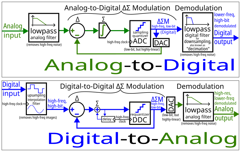 Shows oversampling, 1-bit quantizer, and digital filter. (Image: Em3rgent0rdr, CC0, via Wikimedia Commons)
3. Digital-to-Analog Conversion (DAC)
DAC reconstructs analog signals from digital data. Key parameters:
- Resolution: Number of bits (), determines step size.
- Linearity: Deviation from ideal output.
- Settling Time: Time to reach final value.
3.1 DAC Architectures
| Type | Description | Example Application |
|---|---|---|
| Binary-Weighted | Uses resistors in binary ratio | Fast DACs in communication systems |
| R-2R Ladder | Simplified resistor network | Low-cost DACs in microcontrollers |
| Segmented | Combines binary and thermometer codes | High-speed DACs in D/A converters |
3.2 DAC Error Sources
- Differential Non-Linearity (DNL): Deviation of step size from ideal.
- Integral Non-Linearity (INL): Cumulative error over full range.
- Glitch Impulse: Spikes during bit transitions.
Worked Example:
A 10-bit DAC with has a step size of:
If the digital input is 1010101001₂ (binary), the output voltage is:
4. Signal Reconstruction and Errors
4.1 Aliasing
- Cause: Sampling rate < .
- Effect: High-frequency components appear as lower frequencies.
- Solution: Anti-aliasing filters (low-pass filters before ADC).
4.2 Quantization Noise
- Source: Rounding errors during quantization.
- Reduction: Increase bits or use dithering (adding noise to reduce distortion).
Comparison of Noise Types:
| Noise Type | Cause | Mitigation |
|---|---|---|
| Quantization Noise | Finite resolution | Increase bits or oversampling |
| Aliasing Noise | Insufficient sampling rate | Anti-aliasing filter |
| Thermal Noise | Electronic component heating | Cooling or low-noise components |
## In the real world
eSewa Transactions:
- ADC/DAC Use: eSewa’s backend systems use ADCs to digitize payment signals (e.g., card swipes) and DACs to generate confirmation tones or LED feedback.
- Key Idea: Sampling and quantization ensure transaction data is accurately converted for processing and storage.
Ncell’s Mobile Network:
- ADC Use: Base stations use high-speed ADCs (e.g., Flash or SAR) to sample incoming RF signals for demodulation.
- Example: A 5G signal at 2.6 GHz requires ADCs with sampling rates >10 GHz to avoid aliasing.
Pathao’s Ride-Hailing:
- DAC Use: GPS coordinates from the app are converted to analog signals for display on driver dashboards (e.g., via a small DAC in the in-car system).
- Key Idea: Resolution and linearity ensure accurate route rendering.
NEPSE Stock Data:
- ADC Use: Stock price feeds are digitized via ADCs in trading terminals to log price changes (e.g., 16-bit ADCs for high-resolution data).
- Worked Example: If a stock price changes from Rs. 1000 to Rs. 1000.01, a 12-bit ADC with must resolve steps of ~1.22 mV to capture the change accurately.
5. Data Acquisition Systems (DAS)
A single-channel DAS consists of:
- Sensor: Converts physical quantity (e.g., temperature) to analog signal.
- Signal Conditioning: Amplifies/filters the signal.
- ADC: Converts analog to digital.
- Microcontroller: Processes data (e.g., averages samples).
- Output: Displays or transmits data.
Example: A temperature monitoring system for a server room:
- Sensor: Thermocouple (outputs mV proportional to temperature).
- ADC: 16-bit SAR ADC (e.g., ADC121C021) samples at 1 kHz.
- Calculation: For a range of 0–50°C, the ADC’s LSB represents:
## Exam Tip
Sampling Rate Calculations:
- Always verify . If not, aliasing occurs.
- Example Question: "A signal has frequencies up to 5 kHz. What is the minimum sampling rate?" Answer: (Nyquist rate).
ADC/DAC Comparisons:
- Memorize the trade-offs (speed vs. resolution vs. power) for Flash, SAR, and Delta-Sigma ADCs.
- Example Question: "Which ADC would you use for a heart rate monitor (1 Hz signal, 12-bit resolution)?" Answer: Delta-Sigma ADC (low power, high resolution).
Error Analysis:
- Quantization error = LSB.
- Example Question: "A 10-bit ADC measures 3.45V with . What is the quantization error?"
Steps:
- Calculate LSB: .
- Quantized value: → .
- Error: (±0.5 LSB).
Real-World Applications:
- Link theory to systems like eSewa’s payment processing (ADC for card data) or Ncell’s signal demodulation (DAC for audio).
- Example Question: "How does a smartphone’s microphone use ADC?" Answer: Converts analog sound waves to digital samples (e.g., 44.1 kHz sampling for audio).
Diagrams:
- Draw block diagrams for ADC/DAC architectures and waveforms for aliasing/quantization effects.
- Example: Sketch a Flash ADC with comparators and a Delta-Sigma ADC with oversampling stages.
Key Formula Summary:
| Concept | Formula |
|---|---|
| Nyquist Sampling Rate | |
| ADC Resolution | |
| Quantization Error | |
| DAC Output Voltage |
Based on the PU BE Computer (PU) syllabus for Instrumentation, unit 8.
Discussion
Loading…