Computer ArchitectureUnit 117 min read
Computer Architecture Basics: Definitions, Components & Functional Views
Unit 1 of Computer Architecture introduces the foundational concepts of computer architecture and organization, covering definitions, the IAS architecture, functional components (CPU, memory, I/O), register types, instruction formats, addressing modes, and real-world applications in modern systems.
TAKEAWAYS:
- Computer architecture defines the visible structure (ISA, instruction formats) while organization describes the invisible implementation (circuitry, wiring).
- The IAS architecture (1946) introduced the stored-program concept, separating memory, CPU, and I/O—still the basis for modern computers.
- A CPU’s functional view includes the control unit (fetches/decodes instructions), ALU (performs arithmetic/logic), and registers (fast temporary storage).
- Instruction formats (e.g., 0-address, 1-address) dictate how many operands an instruction carries, affecting efficiency (e.g., stack vs. accumulator architectures).
- Addressing modes (e.g., immediate, indirect, indexed) determine how operands are specified, impacting code size and performance.
- Registers (PC, IR, MAR, MBR, ACC) act as the CPU’s "scratchpad," enabling fast operations but limited in number.
1. Definitions: Architecture vs. Organization
Computer architecture and organization are often confused, but they refer to different levels of abstraction:
classDiagram
    class Architecture {
        +Visible to programmer
        +Instruction Set Architecture (ISA)
        +Instruction formats
        +Addressing modes
        +Memory addressing
    }
    class Organization {
        +Invisible to programmer
        +Hardware implementation
        +Register transfer language (RTL)
        +Control unit design
        +Data paths
    }
    Architecture -->|"Defines"| Organization : "What" to "How"
Key Difference:
| Computer Architecture | Computer Organization |
|---|---|
| What the system does (logical view) | How it does it (physical view) |
| Example: "A CPU has a 32-bit ISA" | Example: "The CPU uses a 5-stage pipeline" |
| Studied by programmers | Studied by hardware engineers |
Why it matters:
- A programmer sees only the architecture (e.g., x86 vs. ARM ISA).
- The organization determines speed, power, and cost (e.g., Intel’s Core i7 vs. Apple’s M1 chip).
2. The IAS Computer Architecture (1946)
The Institute for Advanced Study (IAS) computer, designed by John von Neumann, introduced the stored-program concept, which is the foundation of modern computers. Its architecture included:
Key Features:
- Binary arithmetic: Used for both data and instructions (stored-program concept).
- Memory: 64 words of 40 bits each (1 word = 1 instruction or data).
- Registers:
- Accumulator (AC): Holds operands and results.
- Multiplier-Quotient (MQ): Used for multiplication/division.
- Instruction Register (IR): Holds the current instruction.
- Program Counter (PC): Points to the next instruction.
- I/O: Used punch cards and paper tape (slow by today’s standards).
Real-World Connection:
- Modern CPUs still use the von Neumann architecture, but with caches, pipelining, and multicore designs.
- Example: Your smartphone’s ARM Cortex processor follows this basic structure but with billions of transistors and multi-level caches.
3. Functional View of a Computer
A computer’s operation can be broken down into five functional units, working together in a cycle:
stateDiagram-v2
    [*] --> Fetch
    Fetch --> Decode
    Decode --> Execute
    Execute --> Memory
    Memory --> I/O
I/O --> [*]Components:
- Input Unit: Receives data (keyboard, mouse, sensors).
- Memory Unit: Stores data and instructions (RAM, ROM).
- Arithmetic Logic Unit (ALU): Performs calculations and logic operations.
- Control Unit (CU): Manages instruction execution (fetch-decode-execute cycle).
- Output Unit: Displays results (monitor, printer, speakers).
How It Works:
- Fetch: The CU fetches an instruction from memory using the Program Counter (PC).
- Decode: The instruction is decoded to determine the operation.
- Execute: The ALU performs the operation (e.g., addition, comparison).
- Memory Access: Data is read from/written to memory if needed.
- Output: Results are sent to the output unit.
Worked Example: Adding Two Numbers
Assume we want to compute X = A + B:
- Fetch: PC points to
LOAD A, instruction is fetched into IR. - Decode: CU decodes
LOAD Aand sends signals to loadAinto the Accumulator (AC). - Execute:
Ais loaded into AC. - Fetch: Next instruction (
ADD B) is fetched. - Decode/Execute:
Bis added toAC. - Store: Result (
X) is stored in memory.
4. Registers: The CPU’s Fast Storage
Registers are small, ultra-fast storage locations inside the CPU, used to hold data temporarily. They are limited in number (typically 16–64 in modern CPUs) but much faster than memory.
classDiagram
    class Register {
        +Size: 8-bit to 64-bit
        +Access time: ~1 clock cycle
        +Used for: Temporary storage, instruction pointers, operands
    }
    Register <|-- PC : "Program Counter"
    Register <|-- IR : "Instruction Register"
    Register <|-- MAR : "Memory Address Register"
    Register <|-- MBR : "Memory Buffer Register"
    Register <|-- ACC : "Accumulator"
    Register <|-- SP : "Stack Pointer"
Common Registers and Their Uses:
| Register | Abbreviation | Purpose |
|---|---|---|
| Program Counter | PC | Holds the address of the next instruction to execute. |
| Instruction Register | IR | Holds the current instruction being executed. |
| Memory Address Register | MAR | Holds the memory address of data to be accessed. |
| Memory Buffer Register | MBR | Temporarily holds data read from/written to memory. |
| Accumulator | ACC | Holds intermediate results of arithmetic/logic operations. |
| Stack Pointer | SP | Points to the top of the stack in memory. |
| General Purpose | R0–R15 | Used for temporary data storage (varies by ISA). |
Why Registers Matter:
- Speed: Accessing a register takes ~1 clock cycle, while accessing RAM takes ~100 cycles.
- Efficiency: Reduces memory access, speeding up programs.
- Limitation: Only a few registers exist, so programmers must manage them carefully.
Real-World Example: Pathao’s Ride Allocation When you request a ride on Pathao, the app:
- Uses the PC to fetch the next instruction (e.g., "Check nearest driver").
- The ACC holds the driver’s location data temporarily.
- The SP manages the stack for recursive functions (e.g., pathfinding algorithms).
5. Instruction Formats and Addressing Modes
A. Instruction Formats
Instructions consist of opcode (operation) and operand(s). The format depends on the addressing mode and ISA.
Comparison of Instruction Formats:
| Format | Example | Pros | Cons | Used in |
|---|---|---|---|---|
| 0-address | POP, PUSH |
Simple, no operands needed | Relies on stack | Stack machines (e.g., Java VM) |
| 1-address | LOAD A |
Compact, uses accumulator | Slower (extra STORE needed) |
Early CPUs (e.g., PDP-8) |
| 2-address | ADD A, B |
Balanced, common in RISC | Two operands limit flexibility | ARM, MIPS |
| 3-address | MUL A, B, C |
Flexible, no temporary storage | Longer instructions | CISC (e.g., x86) |
| 4-address | `LD R1, [R2], R3, R4 | Very flexible | Rare, complex hardware | Theoretical designs |
Worked Example: Evaluating X = (M*N) + (P*Q)
Using 3-address instructions:
MUL T1, M, N(T1 = M * N)MUL T2, P, Q(T2 = P * Q)ADD X, T1, T2(X = T1 + T2)
Using 1-address (accumulator):
LOAD MMUL NSTORE T1LOAD PMUL QADD T1STORE X
Why It Matters:
- RISC (Reduced Instruction Set Computing) uses 2-address for simplicity.
- CISC (Complex Instruction Set Computing) uses 3-address for complex operations in fewer instructions.
B. Addressing Modes
Addressing modes determine how operands are specified in an instruction. They affect code size, speed, and flexibility.
classDiagram
    class AddressingMode {
        +Immediate: Operand is part of instruction
        +Direct: Operand is memory address
        +Indirect: Operand is address of address
        +Register: Operand is in a register
        +Register Indirect: Operand is at address in register
        +Indexed: Operand = base + index
        +Relative: Operand = PC + offset
    }
Common Addressing Modes with Examples:
| Mode | Format | Example | Use Case |
|---|---|---|---|
| Immediate | ADD #5 |
ADD R1, #10 |
Loading constants (e.g., loop counters) |
| Direct | ADD [100] |
LOAD [200] |
Accessing memory locations directly |
| Indirect | ADD @R1 |
JMP @PC |
Jump tables, function pointers |
| Register | ADD R1, R2 |
MUL R3, R4 |
Fast operations (no memory access) |
| Register Indirect | ADD @R1 |
STORE @R2 |
Linked lists, dynamic data structures |
| Indexed | ADD R1, R2[R3] |
LOAD R1, ARRAY[R2] |
Array traversal (e.g., for loops) |
| Relative | JMP PC+5 |
CALL SUBROUTINE |
Branching, loops |
Worked Example: Array Traversal in C
for (int i = 0; i < 10; i++) {
    sum += array[i];  // Indexed addressing: array + i
}
- Assembly (x86):
MOV EAX, [ARRAY + EBX](whereEBXholdsi). - Why? Indexed addressing avoids recalculating
array + ievery time.
Real-World Example: Daraz’s Order Processing When you place an order on Daraz:
- The indexed addressing mode is used to access your cart items in memory.
LOAD [CART + INDEX](whereINDEXis your item number).
- The immediate mode loads constants like
TOTAL_ITEMS = 5. - The relative mode handles jumps to different order-processing functions.
6. Bus and Register Transfers
A. Buses: The Data Highway
Buses are shared communication pathways that transfer data between components. There are three main types:
Bus Characteristics:
| Bus | Direction | Width | Example |
|---|---|---|---|
| Data Bus | Bidirectional | 8-bit to 2048-bit | 64-bit data bus in modern CPUs |
| Address Bus | Unidirectional | 16-bit to 64-bit | 32-bit address bus (4GB memory) |
| Control Bus | Bidirectional | Varies | READ, WRITE, RESET signals |
Worked Example: Loading Data from Memory
- Address Bus: CPU sends
0x1000(memory address) to RAM. - Control Bus: CPU sends
READsignal. - Data Bus: RAM sends data at
0x1000back to CPU.
B. Register Transfers
Register transfers move data between registers and memory using buses. They are described in Register Transfer Language (RTL).
Example RTL Operations:
| Operation | RTL Notation | Explanation |
|---|---|---|
| Load Accumulator from Memory | (AC) ← (M[MAR]) |
Load data from memory into AC. |
| Store AC to Memory | (M[MAR]) ← (AC) |
Save AC’s value to memory. |
| Add Two Registers | (AC) ← (AC) + (R1) |
Add R1 to AC, store result in AC. |
| Increment PC | (PC) ← (PC) + 1 |
Move to next instruction. |
Worked Example: ADD R1, R2 in RTL
(MAR) ← (PC)(Load PC into MAR)(MDR) ← (M[MAR])(Fetch instruction from memory)(IR) ← (MDR)(Load instruction into IR)(AC) ← (AC) + (R2)(Add R2 to AC)(PC) ← (PC) + 1(Increment PC)
7. Computer Classification and Flynn’s Taxonomy
Computers are classified based on instruction and data streams. Flynn’s Taxonomy categorizes them into four types:
classDiagram
    class Computer {
        +SISD: Single Instruction, Single Data
        +SIMD: Single Instruction, Multiple Data
        +MISD: Multiple Instruction, Single Data (rare)
        +MIMD: Multiple Instruction, Multiple Data
    }
Comparison Table:
| Type | Description | Examples | Use Cases |
|---|---|---|---|
| SISD | One instruction, one data stream | Von Neumann machines (single-core CPUs) | General-purpose computing (laptops) |
| SIMD | One instruction, multiple data streams | GPUs, vector processors | Graphics rendering, scientific computing |
| MISD | Multiple instructions, one data stream | Rare (theoretical) | Pipeline processing (uncommon) |
| MIMD | Multiple instructions, multiple data streams | Multicore CPUs, clusters | Parallel computing (supercomputers) |
Real-World Examples:
- SISD: Your laptop’s Intel Core i5 (single-core mode).
- SIMD: NVIDIA GPUs (used in gaming and AI training).
- MIMD: Google’s data centers (thousands of servers working in parallel).
In the Real World
eSewa’s Payment Processing
- Uses SIMD in its servers to process thousands of transactions per second (e.g.,
ADD balance, amountapplied to multiple accounts simultaneously). - Registers hold temporary transaction data (e.g.,
ACCstores the new balance). - Indexed addressing accesses user accounts in a database (e.g.,
LOAD [USERS + ID]).
- Uses SIMD in its servers to process thousands of transactions per second (e.g.,
Khalti’s Loan Interest Calculation
- When calculating monthly installments, Khalti’s backend uses:
- 3-address instructions for clarity (e.g.,
MUL principal, rate, time). - Pipelining (Unit 7) to speed up calculations for millions of users.
- 3-address instructions for clarity (e.g.,
- Cache memory (Unit 6) stores frequently accessed loan terms.
- When calculating monthly installments, Khalti’s backend uses:
NTC’s Traffic Route Optimization
- NTC’s traffic management system uses MIMD (multiple sensors, multiple instructions) to:
- SIMD: Process traffic data from all cameras simultaneously (e.g.,
ADD speed1, speed2, ...). - Indexed addressing: Access route data (e.g.,
LOAD [ROUTES + CAMERA_ID]).
- SIMD: Process traffic data from all cameras simultaneously (e.g.,
- Registers hold real-time traffic counts (e.g.,
ACCstores total vehicles on a road).
- NTC’s traffic management system uses MIMD (multiple sensors, multiple instructions) to:
Exam Tip
Definitions First:
- Always define architecture (logical) vs. organization (physical) clearly.
- For IAS architecture, mention binary arithmetic, stored-program concept, and registers (AC, MQ, IR, PC).
Diagrams Are Mandatory:
- Draw the IAS architecture block diagram (memory, CPU, I/O).
- Show instruction formats (0-, 1-, 2-, 3-address) with examples.
- Illustrate addressing modes with memory diagrams (e.g., indirect vs. indexed).
Worked Examples:
- For addressing modes, show how
array[i]is accessed using indexed addressing. - For instruction formats, compare 3-address vs. 1-address for the same operation (e.g.,
X = A + B).
- For addressing modes, show how
Real-World Links:
- Connect registers to app performance (e.g., "Why does Pathao need fast registers?").
- Relate Flynn’s Taxonomy to Nepali tech (e.g., "How does Ncell’s 5G use SIMD?").
Common Pitfalls:
- Don’t confuse:
- Addressing modes (how operands are specified) vs. instruction formats (how many operands).
- Bus types (data, address, control) vs. register transfers (RTL operations).
- Avoid vague answers: Always give examples (e.g., "Indexed addressing is used in
forloops").
- Don’t confuse:
Past Exam Patterns:
- Part (a): Define and explain (e.g., "Differentiate architecture and organization").
- Part (b): Compare or apply (e.g., "Evaluate
X = (M*N) + (P*Q)using 3-address instructions"). - Diagrams: Always include block diagrams for architectures and memory diagrams for addressing modes.
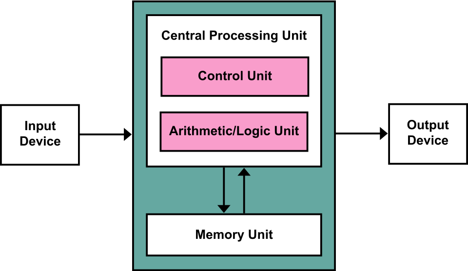 Block diagram of the IAS computer showing memory, CPU, and I/O units (Image: Kapooht, CC BY-SA 3.0, via Wikimedia Commons)
Based on the PU BE Computer (PU) syllabus for Computer Architecture, unit 1.
Discussion
Loading…