Computer ArchitectureUnit 212 min read
Processor Architecture & Registers: Types, Roles & CPU Internals
Unit 2 of Computer Architecture explores the internal structure of processors, the role of registers in CPU operations, and how modern processors organize their components for efficient execution. Learn about register types, their functions, and how they interact with the ALU, control unit, and memory.
TAKEAWAYS:
- Registers are the CPU’s ultra-fast memory: They store operands, instructions, and intermediate results, reducing access time from microseconds (main memory) to nanoseconds.
- Registers are classified by function: General-purpose (e.g., AX, BX), special-purpose (e.g., PC, SP), and floating-point registers (e.g., FP0-FP7) each serve distinct roles in instruction execution.
- The CPU’s core components work in tandem: The ALU performs arithmetic/logic operations, the control unit decodes instructions, and registers hold data/addresses for rapid access.
- Register transfer language (RTL) describes data movement: It uses symbols like
A ← B + Cto represent how data flows between registers and the ALU. - Modern processors use hierarchical registers: For example, Intel’s x86-64 has 16 general-purpose registers (RAX, RBX, etc.), while ARM’s NEON SIMD registers handle parallel data processing.
- Registers enable pipelining and parallelism: By holding intermediate results, they allow the CPU to overlap instruction fetch, decode, execute, and write-back stages.
1. Introduction to Processor Architecture
The processor (CPU) is the brain of a computer, responsible for executing instructions and performing computations. Its architecture defines how it interacts with memory, input/output devices, and software. Key components include:
- Arithmetic Logic Unit (ALU): Performs arithmetic (addition, subtraction) and logic operations (AND, OR, NOT).
- Control Unit (CU): Decodes instructions and coordinates data flow between components.
- Registers: Small, ultra-fast storage locations inside the CPU.
- Cache Memory: High-speed memory between CPU and RAM to reduce latency.
How the CPU Works: A Simplified View
stateDiagram-v2
[*] --> Fetch: Instruction from memory
Fetch --> Decode: Control Unit interprets opcode
Decode --> Execute: ALU performs operation
Execute --> MemoryAccess: Read/write data if needed
MemoryAccess --> WriteBack: Store result in register
WriteBack --> [*]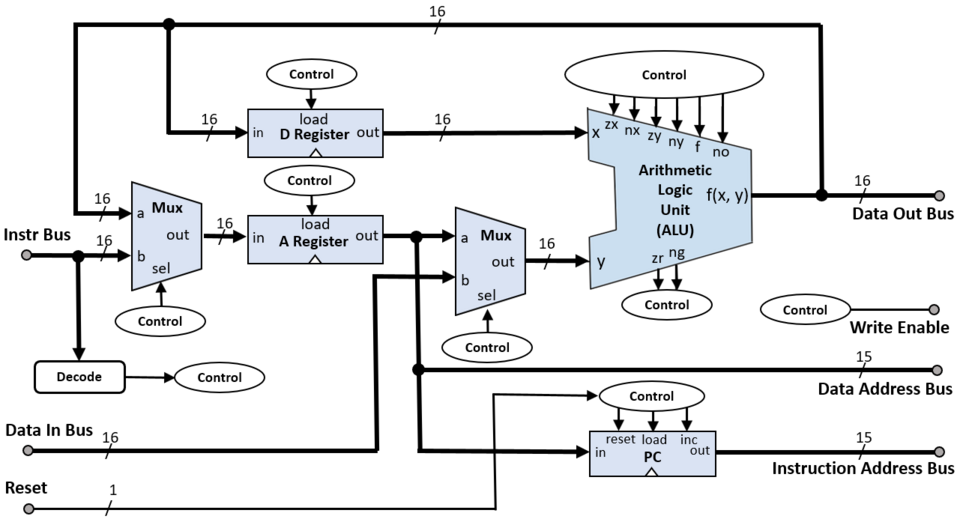 A labelled diagram showing the ALU, control unit, registers, and data paths inside a CPU. (Image: Rleininger, CC BY-SA 4.0, via Wikimedia Commons)
2. Types of Registers in a CPU
Registers are classified based on their function. Below is a table summarizing the most common types:
| Register Type | Examples (x86) | Function |
|---|---|---|
| General-Purpose | AX, BX, CX, DX | Store operands, addresses, and intermediate results. |
| Special-Purpose | PC (Program Counter), SP (Stack Pointer), IP (Instruction Pointer) | Manage program flow and memory access. |
| Floating-Point | FP0-FP7 (x87), XMM0-XMM7 (SSE) | Handle floating-point arithmetic (e.g., scientific calculations). |
| Segment | CS, DS, SS, ES | Store memory segment addresses (used in segmented architectures like x86). |
| Status/Flag | FLAGS (e.g., ZF, CF) | Indicate results of operations (e.g., Zero Flag, Carry Flag). |
| Instruction | IR (Instruction Register) | Holds the current instruction being executed. |
Real-World Example: Registers in a Bank Loan Calculation
Imagine a bank’s loan processing system (like Nabil Bank’s online loan calculator). When you input:
- Principal (P) = ₹500,000
- Interest Rate (R) = 8% per annum
- Time (T) = 5 years
The CPU uses registers to store:
- AX: Principal amount (₹500,000)
- BX: Interest rate (8)
- CX: Time (5)
- FP0: Temporary floating-point result (e.g., )
- FP1: Final EMI (Equated Monthly Installment) calculation.
The ALU performs:
SI = (P * R * T) / (100 * 12 * T) // Simplified EMI formula
Registers hold intermediate values like SI until the final result is stored in memory.
3. Role of Registers in CPU Operations
Registers play three critical roles:
- Temporary Storage: Hold operands and results during instruction execution.
- Example:
ADD AX, BX→ AX and BX are registers storing operands; the result is stored back in AX.
- Example:
- Instruction Pointer Management: The Program Counter (PC) holds the address of the next instruction to fetch.
- Status Tracking: Flag registers (e.g., Zero Flag, Carry Flag) indicate the outcome of operations (e.g., overflow, division by zero).
stateDiagram-v2
    [*] --> Fetch: IR ← Memory[PC]
    Fetch --> Decode: Control Unit reads IR
    Decode --> Execute: ALU ← AX + BX
    Execute --> WriteBack: AX ← ALU_result
    WriteBack --> [*]
    note right of Execute
        Registers hold operands
        and results during
        each stage
    end note
Register involvement in the fetch-decode-execute-writeback cycleRegister Transfer Language (RTL)
RTL is a notation to describe how data moves between registers and the ALU. Example:
IR ← Memory[PC]      // Fetch instruction from memory
PC ← PC + 1           // Increment PC
ALU ← AX + BX         // Perform addition
FLAGS ← ALU_status    // Update flags (e.g., Zero Flag)
AX ← ALU_result       // Store result in AX
Worked Example: Adding Two Numbers Using RTL
Instruction: ADD AX, BX
RTL Steps:
IR ← Memory[PC](FetchADD AX, BX)PC ← PC + 1(Move to next instruction)ALU ← AX + BX(Perform addition)FLAGS ← ALU_status(Set flags if result is zero or overflow occurs)AX ← ALU_result(Store result in AX)
4. Special-Purpose Registers and Their Functions
a) Program Counter (PC)
- Holds the address of the next instruction to execute.
- Automatically increments after each instruction fetch (unless altered by jumps/calls).
- Example: In a loop, the PC ensures instructions are executed sequentially.
b) Stack Pointer (SP)
- Points to the top of the stack memory (a region of RAM used for function calls and local variables).
- Example: When a function is called, the return address is pushed onto the stack, and SP is decremented.
c) Instruction Register (IR)
- Holds the current instruction being executed.
- The control unit decodes the opcode (operation code) from IR.
d) Flag Registers
- Zero Flag (ZF): Set if the result of an operation is zero.
- Carry Flag (CF): Set if an arithmetic operation generates a carry/borrow.
- Overflow Flag (OF): Set if signed arithmetic overflows (e.g., in an 8-bit register).
5. Registers in Modern Processors
Modern processors (e.g., Intel Core i7, ARM Cortex-A76) use hierarchical registers and vector registers for parallel processing.
a) x86-64 Registers (Intel/AMD)
- General-Purpose: 16 registers (RAX, RBX, RCX, RDX, RSI, RDI, RBP, RSP, R8-R15).
- Floating-Point: XMM0-XMM15 (128-bit SIMD registers for multimedia instructions).
- Control Registers: CR0-CR4 (manage CPU modes, paging, and protection).
b) ARM Registers (e.g., Cortex-A Series)
- General-Purpose: R0-R15 (R15 is the PC).
- NEON SIMD: Q0-Q31 (128-bit registers for parallel data processing, used in apps like WhatsApp’s image compression).
c) Floating-Point Registers (FPU)
- Used in scientific computing (e.g., Nepal Electricity Authority’s load forecasting models).
- Example:
FADD FP0, FP1adds two floating-point numbers stored in FP0 and FP1.
6. Register Transfer Operations
Register transfers describe how data moves between registers and the ALU. Common operations include:
- Data Transfer:
A ← B(Copy data from B to A). - Arithmetic:
A ← B + C(Add B and C, store in A). - Logic:
A ← B AND C(Bitwise AND). - Shift/Rotate:
A ← B << 2(Shift B left by 2 bits).
Example: Multiplication Using RTL
Instruction: MUL AX, BX (Multiply AX by BX)
RTL Steps:
IR ← Memory[PC]PC ← PC + 1ALU ← AX * BX(Perform multiplication)FLAGS ← ALU_status(Check for overflow)DX:AX ← ALU_result(Store 32-bit result in DX and AX)
7. Registers in Real-World Systems
a) eSewa and Khalti (Digital Payments)
When you transfer money via eSewa:
- The PC fetches the payment instruction from the app’s code.
- General-purpose registers (e.g., RAX, RBX) store the sender’s account number, amount, and receiver’s details.
- The ALU calculates the deducted balance and updates the transaction log.
- Flag registers ensure the transaction is successful (e.g., no overflow in the balance).
b) Pathao’s Ride-Hailing Algorithm
Pathao’s driver-matching system uses registers to:
- Store driver locations (e.g., in XMM registers for parallel processing).
- Compare distances using floating-point registers (FP0-FP7).
- Update the PC to fetch the next passenger request.
c) NTC’s Traffic Management System
NTC’s traffic light control system (used in Kathmandu’s busy intersections) relies on:
- Timer registers to control light durations.
- Status flags to detect traffic density (e.g., using sensors).
- PC to cycle through predefined traffic patterns.
8. Comparison: Single-Core vs. Multi-Core Processors
While this unit focuses on uniprocessor systems, understanding multi-core architectures helps contextualize register usage.
| Feature | Single-Core Processor | Multi-Core Processor (Dual/Quad Core) |
|---|---|---|
| Registers | Shared among all threads. | Each core has its own set of registers. |
| Parallelism | Limited to instruction-level parallelism (pipelining). | True parallelism (multiple instructions executed simultaneously). |
| Performance | Slower for multi-threaded tasks. | Faster for tasks like video rendering (e.g., YouTube’s encoding). |
| Software Optimization | Easier to program (no race conditions). | Requires thread-safe code (e.g., WhatsApp’s backend servers). |
| Power Consumption | Lower (single ALU). | Higher (multiple ALUs and caches). |
9. Exam Tip: How to Score Full Marks
- Define Clearly: Always start with precise definitions (e.g., "Registers are high-speed storage locations inside the CPU used to hold operands, instructions, and intermediate results").
- Use RTL for Worked Examples: Examiners love step-by-step RTL traces. For example:
- Question: Explain how
SUB AX, BXworks using RTL. - Answer:
IR ← Memory[PC]
PC ← PC + 1
ALU ← AX - BX
FLAGS ← ALU_status (e.g., set ZF if result is zero)
AX ← ALU_result
- Question: Explain how
- Compare Register Types: Use tables to differentiate general-purpose, special-purpose, and floating-point registers.
- Relate to Real-World Scenarios: Link registers to systems like eSewa’s payment processing or Pathao’s driver matching.
- Draw Diagrams: Sketch the CPU’s internal structure (ALU, registers, control unit) and label key components.
- Mention Modern Architectures: Briefly discuss x86-64 or ARM registers to show awareness of contemporary systems.
Common Pitfalls to Avoid:
- Confusing registers with cache memory (registers are inside the CPU; cache is between CPU and RAM).
- Forgetting to mention flag registers in discussions about status tracking.
- Not using RTL notation in worked examples (always include it for full marks).
In the real world
- Nepali Banks' Loan Processing: Uses general-purpose registers (AX, BX) to store principal amounts (₹500,000) and floating-point registers (FP0-FP7) for EMI calculations in their server CPUs (e.g., Nabil Bank's backend systems).
- Pathao Driver App: Employs SIMD registers (XMM0-XMM15) for parallel processing of multiple ride requests simultaneously on mobile CPUs (ARM Cortex-A78).
- NTC's Network Monitoring: Relies on special-purpose registers (PC, SP) to manage instruction flow in routers (Cisco ASR 1000 series) handling Nepal's internet traffic routing.
Based on the PU BE Computer (PU) syllabus for Computer Architecture, unit 2.
Discussion
Loading…