Computer NetworksUnit 216 min read
Network Models: Topologies, Devices & OSI/TCP-IP
Unit 2 of Computer Networks covers network topologies (star, bus, ring, mesh), network devices (hub, switch, bridge, router), proxy servers, HTTP/HTTPS, and OSI vs. TCP/IP models, with real-world applications in Nepal’s tech ecosystem (e.g., Ncell’s routing, eSewa’s security, Daraz’s congestion control).
TAKEAWAYS:
- Topologies determine how devices connect (star = central hub; mesh = every node connected) and impact cost, scalability, and fault tolerance.
- Network devices (hub → switch → router) filter, forward, or route traffic based on MAC/IP addresses, with routers enabling inter-network communication.
- Proxy servers cache content (e.g., NTC’s ISP proxy) and enforce security policies, while HTTPS adds encryption (used by Khalti for payments).
- OSI (7 layers) is a theoretical model; TCP/IP (4 layers) is the practical standard (used by all internet protocols, including WhatsApp’s signaling).
- Congestion occurs when traffic exceeds network capacity (e.g., Pathao’s delivery queues during festivals), requiring mechanisms like TCP’s slow-start.
- Exam focus: Compare topologies/devices, explain OSI/TCP-IP layer functions, and trace packet flows (e.g., DNS lookup → HTTP request).
1. Network Topologies: How Devices Connect
Topology defines the physical or logical arrangement of devices in a network. It affects cost, scalability, fault tolerance, and performance. Below are the four key topologies, compared in a table and visualized.
1.1 Star Topology
- Definition: All devices connect to a central node (e.g., switch, hub). If the central node fails, the entire network collapses.
- How it works:
- Data from any device travels through the central node to reach others.
- Example: Home Wi-Fi router connecting laptops, phones, and smart TVs.
- Advantages:
- Easy to install/maintain.
- Fault isolation (one device failure doesn’t crash the network).
- Scalable (add devices by connecting to the central node).
- Disadvantages:
- Single point of failure (central node).
- Higher cost for cabling/wiring.
- Real-world example:
- Ncell’s mobile network: Base stations (central nodes) connect to user devices via radio waves (logical star).
- Khalti’s payment gateway: Servers act as central nodes for merchant transactions.
graph TD
    A["Central Node\n(Switch/Hub)"] --> B["Device 1"]
    A --> C["Device 2"]
    A --> D["Device 3"]
1.2 Bus Topology
- Definition: All devices share a single communication line (bus). Data is broadcast to all devices, but only the intended recipient processes it.
- How it works:
- Uses a backbone cable (e.g., Ethernet coaxial cable).
- Terminators at both ends prevent signal reflection.
- Advantages:
- Low cost (minimal cabling).
- Easy to add/remove devices.
- Disadvantages:
- Single point of failure (bus failure = network down).
- Performance degrades as more devices join (collisions increase).
- Hard to troubleshoot (all devices share the same line).
- Real-world example:
- Old LAN setups in offices (rare today, but used in legacy systems).
- Traffic signals in Kathmandu: Cars (devices) share a "virtual bus" (road), but only the next signal (recipient) acts.
graph LR
    A["Device 1"] -- Bus Cable --> B["Device 2"]
    B --> C["Device 3"]
    C --> D["Terminator"]
1.3 Ring Topology
- Definition: Devices are connected in a closed loop, with data traveling in one direction (unidirectional) or both (bidirectional).
- How it works:
- Each device acts as a repeater, forwarding data to the next node.
- Uses token-passing (e.g., Token Ring protocol) to avoid collisions.
- Advantages:
- No collisions (token ensures only one device transmits at a time).
- Equal access for all devices.
- Disadvantages:
- Single point of failure (break in the ring = network down).
- Difficult to add/remove devices (requires network shutdown).
- Performance bottleneck if one device fails.
- Real-world example:
- Fiber-optic metro networks in cities (e.g., NTC’s backbone).
- Factory assembly lines: Robots (devices) pass tasks (tokens) in a loop.
graph TD
    A["Device 1"] --> B["Device 2"]
    B --> C["Device 3"]
    C --> D["Device 4"]
    D --> A
1.4 Mesh Topology
- Definition: Every device is connected to every other device (full mesh) or to some devices (partial mesh).
- How it works:
- Data has multiple paths to reach the destination (redundancy).
- Used in high-reliability networks (e.g., military, aerospace).
- Advantages:
- High fault tolerance (no single point of failure).
- Scalable (add devices without disrupting the network).
- High performance (multiple paths reduce congestion).
- Disadvantages:
- Expensive (requires many cables/wiring).
- Complex management (hard to configure).
- Real-world example:
- Air traffic control systems: Radars (devices) communicate via multiple redundant links.
- Nepal Electricity Authority’s grid: Power substations (nodes) have backup routes.
graph TD
    A["Device 1"] --> B["Device 2"]
    A --> C["Device 3"]
    A --> D["Device 4"]
    B --> C
    B --> D
    C --> D
1.5 Comparison Table
| Topology | Central Node | Cabling Cost | Fault Tolerance | Scalability | Best For |
|---|---|---|---|---|---|
| Star | Yes (switch/hub) | High | Low (central node) | High | Homes, offices, campuses |
| Bus | No | Low | Very Low | Medium | Legacy LANs |
| Ring | No | Medium | Low (ring break) | Low | Token Ring networks |
| Mesh | No | Very High | Very High | Very High | Military, aerospace |
2. Network Devices: How Data Moves
Network devices filter, forward, or route data between networks. Their functionality depends on the OSI layer they operate in.
2.1 Hub (Physical Layer)
- Function: Operates at Layer 1 (Physical). Broadcasts all incoming data to all ports (no filtering).
- How it works:
- Receives a signal → amplifies it → sends to all connected devices.
- No intelligence: Causes collisions in half-duplex networks.
- Example:
- Old 10 Mbps Ethernet hubs (now obsolete).
- Real-world analogy:
- A megapphone where everyone hears every call.
graph TD
    A["Hub"] --> B["Device 1"]
    A --> C["Device 2"]
    A --> D["Device 3"]
2.2 Switch (Data Link Layer)
- Function: Operates at Layer 2 (Data Link). Uses MAC addresses to forward data only to the intended device.
- How it works:
- Builds a MAC address table (maps MAC addresses to ports).
- Reduces collisions by segmenting the network.
- Example:
- Home/office Ethernet switches.
- Real-world example:
- Daraz’s order processing: Switches route packets between servers and customers’ devices.
graph TD
    A["Switch"] -->|"MAC Address"| B["Device 1"]
    A -->|"MAC Address"| C["Device 2"]
2.3 Bridge (Data Link Layer)
- Function: Operates at Layer 2. Connects two separate LAN segments and filters traffic based on MAC addresses.
- How it works:
- Learns MAC addresses on each segment.
- Forwards traffic only if the destination is on the other segment.
- Example:
- Connecting two Ethernet networks in a large office.
- Real-world analogy:
- A border checkpoint between two cities (only lets through relevant traffic).
graph TD
    A["LAN 1"] --> B["Bridge"]
    C["LAN 2"] --> B
2.4 Router (Network Layer)
- Function: Operates at Layer 3 (Network). Connects different networks (e.g., LAN to WAN) using IP addresses.
- How it works:
- Uses routing tables to determine the best path.
- Performs NAT (Network Address Translation) to share a single public IP.
- Example:
- Home Wi-Fi router (connects LAN to ISP).
- Real-world example:
- Ncell’s core routers: Route data between mobile towers and the internet.
graph TD
    A["LAN"] --> B["Router"]
    B --> C["WAN\n(Internet)"]
2.5 Comparison Table
| Device | Layer | Addressing | Function | Example |
|---|---|---|---|---|
| Hub | 1 | None | Broadcasts to all ports | Old Ethernet hub |
| Switch | 2 | MAC | Forwards to specific MAC | Cisco Catalyst Switch |
| Bridge | 2 | MAC | Connects two LAN segments | Legacy network bridge |
| Router | 3 | IP | Connects networks (LAN ↔ WAN) | Home Wi-Fi router |
3. Proxy Servers: Caching and Security
A proxy server acts as an intermediary between clients and servers. It can:
- Cache content (reduce bandwidth usage).
- Filter requests (block malicious sites).
- Hide client IP addresses (anonymity).
3.1 How a Proxy Server Works
- Client sends a request to the proxy.
- Proxy checks its cache for the content.
- If found (cache hit), sends it directly.
- If not (cache miss), forwards the request to the real server.
- Proxy receives the response → sends it to the client.
3.2 Real-world Examples
- NTC’s ISP Proxy: Caches popular websites (e.g., YouTube) to reduce load on international links.
- Corporate Proxies: Block access to social media (e.g., Facebook) during work hours.
- VPNs: Use proxy-like servers to mask user locations (e.g., accessing Netflix US from Nepal).
3.3 HTTP vs. HTTPS
| Feature | HTTP | HTTPS |
|---|---|---|
| Security | No encryption (plaintext) | Encrypted (SSL/TLS) |
| Port | 80 | 443 |
| Use Case | Internal networks, testing | E-commerce (Khalti, Daraz), banking |
| Speed | Faster (no encryption overhead) | Slightly slower |
Example:
- Khalti’s payment page uses HTTPS to encrypt credit card details.
- eSewa’s login uses HTTPS to prevent man-in-the-middle attacks.
4. OSI vs. TCP/IP Models: The Two Network Standards
Both models describe how data is transmitted across networks, but they differ in layers and practical use.
4.1 OSI Model (7 Layers)
A theoretical model for understanding network functions. Rarely implemented in practice but useful for troubleshooting.
| Layer | Name | Function | Protocol/Data Unit |
|---|---|---|---|
| 7 | Application | User interfaces (e.g., HTTP, FTP) | Data |
| 6 | Presentation | Data translation (e.g., encryption) | Data |
| 5 | Session | Manages sessions (e.g., NetBIOS) | Data |
| 4 | Transport | End-to-end communication (TCP/UDP) | Segments |
| 3 | Network | Routing (IP, ICMP) | Packets |
| 2 | Data Link | Framing (MAC, Ethernet) | Frames |
| 1 | Physical | Raw bit transmission (cables, signals) | Bits |
Example Trace (Email):
- Application: Your email client (Gmail) sends data.
- Presentation: Data is formatted (e.g., ASCII to binary).
- Session: Connection is established with the server.
- Transport: TCP breaks data into segments.
- Network: IP addresses the packets.
- Data Link: MAC addresses frame the data.
- Physical: Bits are sent as electrical signals.
4.2 TCP/IP Model (4 Layers)
A practical model used by the internet. Combines OSI’s layers for efficiency.
| Layer | Name | Function | Protocol/Data Unit |
|---|---|---|---|
| 4 | Application | OSI’s Layers 5-7 (HTTP, DNS, FTP) | Data |
| 3 | Transport | TCP/UDP | Segments |
| 2 | Internet | IP, ICMP, ARP | Packets |
| 1 | Network Access | OSI’s Layers 1-2 (Ethernet, Wi-Fi) | Frames/Bits |
Real-world example:
- WhatsApp messages:
- Application: Your phone sends a message (HTTP/HTTPS).
- Transport: TCP ensures reliable delivery.
- Internet: IP routes the packet to WhatsApp’s server.
- Network Access: Wi-Fi/Ethernet transmits the frame.
4.3 Why TCP/IP Wins
- Simpler: Fewer layers → easier to implement.
- Backward compatible: Works with existing protocols.
- Used everywhere: Internet, intranets, and even OSI-based networks rely on TCP/IP.
5. Congestion Control: Keeping Networks Flowing
Congestion occurs when traffic exceeds network capacity, causing:
- Packet loss.
- Increased latency.
- Network collapse.
5.1 Causes of Congestion
- Too many devices (e.g., festival season on Pathao’s servers).
- Large files (e.g., downloading a movie on slow Wi-Fi).
- Malicious traffic (DDoS attacks).
5.2 TCP Congestion Control Mechanisms
TCP uses four algorithms to manage congestion:
- Slow Start:
- Starts with a small congestion window (CWND).
- Exponentially increases CWND until loss is detected.
- Congestion Avoidance:
- Linearly increases CWND to avoid sudden overload.
- Fast Retransmit:
- Detects duplicate ACKs → retransmits lost packets.
- Fast Recovery:
- Reduces CWND sharply after loss but avoids slow start.
Example:
- Downloading a file from Daraz:
- TCP starts with a small window → speeds up → detects congestion → slows down.
5.3 Real-world Impact
- Pathao’s delivery system: Uses congestion control to prioritize high-priority orders during Dashain.
- Ncell’s 4G network: Dynamically adjusts bandwidth for calls vs. data.
## In the Real World
Ncell’s Mobile Network:
- Uses mesh-like redundancy in its core routers to handle call drops during festivals.
- Routing protocols (OSPF/BGP) dynamically reroute traffic if a tower fails.
eSewa’s Payment Gateway:
- Proxy servers cache frequent transactions (e.g., utility bill payments) to reduce latency.
- HTTPS encrypts all financial data to prevent fraud.
Daraz’s Order Fulfillment:
- Star topology connects warehouses (central nodes) to delivery agents.
- TCP congestion control ensures orders are processed even during sales like "Daraz Days."
NTC’s Internet Backbone:
- Ring topology connects major cities (Kathmandu, Pokhara, Biratnagar) for redundancy.
- Routers use BGP (Border Gateway Protocol) to route international traffic efficiently.
## Exam Tip
Topologies:
- Star = central node; Mesh = no single point of failure.
- Bus/Ring are obsolete but may appear in comparisons.
- Draw diagrams in exams (label devices and data flow).
Devices:
- Hub = Layer 1 (broadcasts to all).
- Switch = Layer 2 (uses MAC addresses).
- Router = Layer 3 (uses IP addresses).
- Memorize the comparison table.
OSI vs. TCP/IP:
- OSI is theoretical (7 layers); TCP/IP is practical (4 layers).
- Trace a packet’s journey (e.g., email) through layers in exams.
Congestion Control:
- TCP’s slow start and congestion avoidance are key.
- Relate to real examples (e.g., Pathao’s order queue).
Proxy Servers & HTTPS:
- Proxy = caches/filters; HTTPS = encrypts (use in banking apps).
- Compare HTTP/HTTPS in a table (security, port, use case).
Common Pitfalls:
- Don’t confuse MAC (Layer 2) and IP (Layer 3) addressing.
- Ring topology requires token passing; bus is collision-prone.
- Routers work with IP; switches with MAC.
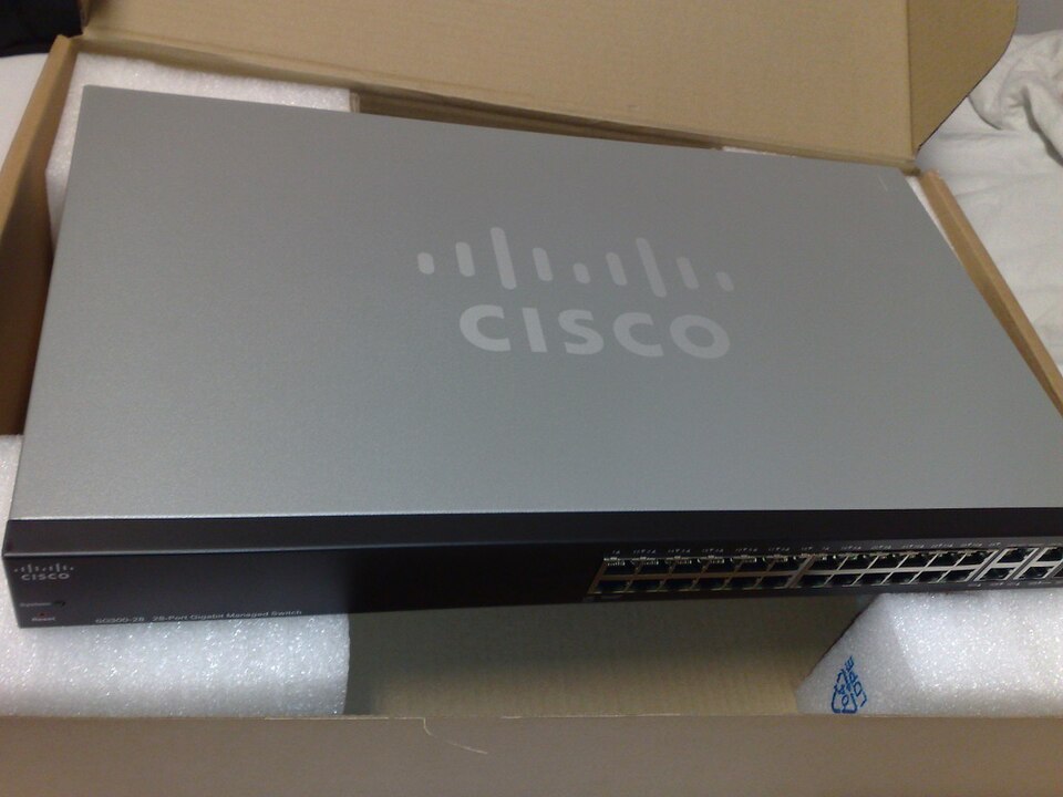 A real Cisco Catalyst switch with ports and LEDs (Image: Dsimic, CC BY-SA 3.0, via Wikimedia Commons)
Based on the PU BE Computer (PU) syllabus for Computer Networks, unit 2.
Discussion
Loading…