Digital LogicUnit 713 min read
Digital System Design: Architectures, ALUs, MUXes & Real-World Apps
Unit 7 of Digital Logic covers the principles of designing digital systems, including arithmetic logic units (ALUs), multiplexers, decoders, and practical applications like memory design, code converters, and real-world systems in Nepal (e.g., Ncell billing, eSewa transactions, and Daraz order processing). This note ex
Key Concepts in Digital System Design
1. Digital System Architectures
Digital systems are built using combinational (gates, MUXes, decoders) and sequential (flip-flops, counters, registers) circuits. Their design follows structured steps:
A. System Design Methodology
- Problem Analysis: Define inputs, outputs, and constraints (e.g., speed, cost).
- Logic Design: Use Boolean algebra, K-maps, or HDL (VHDL/Verilog).
- Circuit Implementation: Combine gates, MUXes, decoders, and registers.
- Verification: Test with truth tables, timing diagrams, or simulators.
- Optimization: Reduce components, power, or delay.
B. Block Diagrams of Key Components
Digital systems often include:
- Arithmetic Logic Unit (ALU): Performs arithmetic (addition, subtraction) and logic (AND, OR, NOT) operations.
- Multiplexer (MUX): Selects one of many inputs based on control signals.
- Decoder: Converts coded inputs (e.g., binary) into active outputs (e.g., segment displays).
- Registers & Counters: Store and sequence data.
2. Arithmetic Logic Unit (ALU)
The ALU is the brain of a CPU, performing operations like:
- Arithmetic: Addition, subtraction, multiplication (via repeated addition).
- Logic: AND, OR, NOT, XOR, NAND, NOR.
Example: 4-bit ALU Design
An ALU can be designed using:
- Full Adders (FA) for arithmetic.
- Logic Gates for operations like AND/OR.
       +-----------+
       |   ALU     |
       |           |
       +-----+-----+
              |
       +------v------+
       | Control Unit|
       +------------+
Worked Example: Design a 4-bit ALU that performs addition and AND.
- Use 4 Full Adders for addition.
- Use 4 AND gates for bitwise AND.
- Use a 2:1 MUX to select between addition and AND based on a control signal (
S0).
| Operation | Control Signal (S0) |
Output |
|---|---|---|
| Addition | 0 | A + B |
| AND | 1 | A AND B |
Real-World Tie-In:
- Ncell Billing System: Uses ALUs to calculate call durations, data usage, and bill amounts in real time.
- eSewa Transactions: ALUs verify transaction amounts and update account balances instantly.
3. Multiplexers (MUXes) and Demultiplexers (DEMUXes)
A. Multiplexer (MUX)
- Function: Selects one of
2^ninputs based onnselect lines. - Example: A 4:1 MUX has 4 inputs (
I0-I3), 2 select lines (S1, S0), and 1 output (Y).
| S1 | S0 | Selected Input | Output (Y) |
|---|---|---|---|
| 0 | 0 | I0 | I0 |
| 0 | 1 | I1 | I1 |
| 1 | 0 | I2 | I2 |
| 1 | 1 | I3 | I3 |
Worked Example:
Design a circuit to select between two 4-bit numbers (A and B) based on a control signal (Sel).
- Use 4 2:1 MUXes (one per bit) with
Selas the select line.
       +-----+       +-----+
       |     |       |     |
Sel ---| MUX |-------| MUX |
       |     |       |     |
       +--+--+       +--+--+
          |           |
       +--v--+   +--v--+
       |     |   |     |
       | A3  |   | B3  |
       |     |   |     |
       +-----+   +-----+
Real-World Tie-In:
- Pathao Ride Selection: Uses MUXes to select the nearest driver based on GPS data and passenger location.
- Daraz Order Processing: MUXes prioritize orders based on payment status (paid vs. pending).
B. Demultiplexer (DEMUX)
- Function: Routes a single input to one of
2^noutputs based on select lines. - Example: A 1:4 DEMUX has 1 input (
I), 2 select lines (S1, S0), and 4 outputs (Y0-Y3).
| S1 | S0 | Selected Output |
|---|---|---|
| 0 | 0 | Y0 |
| 0 | 1 | Y1 |
| 1 | 0 | Y2 |
| 1 | 1 | Y3 |
Worked Example:
Design a circuit to light up one of four LEDs based on a 2-bit input (S1, S0).
- Use a 1:4 DEMUX with
S1, S0as select lines and LEDs connected to outputs.
       +-----+
       | DEMUX|
I ---->|     |
       |     |
       +--+--+
          |
       +--v--+
       | LEDs |
       | Y0-Y3|
       +------+
Real-World Tie-In:
- NTC Traffic Light Control: DEMUXes route signals to different roads based on sensor inputs (e.g., traffic density).
- Khalti Payment Routing: DEMUXes direct transactions to the correct merchant account.
4. Decoders and Encoders
A. Decoder
- Function: Converts
ninput lines into2^nactive outputs. - Example: A 2:4 Decoder has inputs (
A1, A0) and outputs (Y0-Y3).
| A1 | A0 | Active Output |
|---|---|---|
| 0 | 0 | Y0 |
| 0 | 1 | Y1 |
| 1 | 0 | Y2 |
| 1 | 1 | Y3 |
Worked Example:
Design a 7-segment display decoder for a binary input (A2-A0).
- Use a 3:8 Decoder to activate the correct segments (e.g.,
Y0for "a",Y1for "b").
       +-----------+
       | 3:8 Decoder|
A2,A0--|            |
       |            |
       +--+---------+
          |
       +--v--+
       | 7-Segment|
       | Display  |
       +----------+
Real-World Tie-In:
- Digital Clocks (e.g., in buses): Use decoders to display time on 7-segment LEDs.
- ATM Machines: Decoders select the correct card slot based on input codes.
B. Encoder
- Function: Converts
2^ninputs intonoutput lines. - Example: A 4:2 Encoder has 4 inputs (
I0-I3) and 2 outputs (A1, A0).
| Active Input | A1 | A0 |
|---|---|---|
| I0 | 0 | 0 |
| I1 | 0 | 1 |
| I2 | 1 | 0 |
| I3 | 1 | 1 |
Worked Example: Design an encoder for a priority interrupt system where higher-priority inputs override lower ones.
- Use priority logic (e.g.,
I3 > I2 > I1 > I0).
Real-World Tie-In:
- Nepal Stock Exchange (NEPSE) Ticker: Encodes stock prices into binary for display.
- Emergency Call Systems: Encoders prioritize calls based on urgency (e.g., fire > medical).
5. Memory Units (RAM, ROM)
Digital systems store data using:
- RAM (Random Access Memory): Volatile, used for temporary storage (e.g., CPU cache).
- ROM (Read-Only Memory): Non-volatile, stores permanent data (e.g., firmware).
A. RAM Organization
- Example: A 4x4 RAM has 4 words of 4 bits each.
- Address Decoder: Selects the correct word using binary addresses.
       +-----------+
       | Address   |
       | Decoder   |
       +-----+-----+
            |
       +-----v-----+
       |           |
       | 4x4 RAM    |
       | (16 bits)  |
       +-----+-----+
            |
       +-----v-----+
       | Data Bus   |
       +------------+
Worked Example:
Design a 4-bit register file with 2 registers (R0, R1).
- Use a 1:2 DEMUX to select the register and latches to store data.
B. ROM Organization
- Example: A 4x4 ROM stores fixed data (e.g., lookup tables).
- Fuse/Flash Technology: Used in modern ROMs (e.g., BIOS chips).
       +-----------+
       | Address   |
       | Decoder   |
       +-----+-----+
            |
       +-----v-----+
       |           |
       | 4x4 ROM    |
       | (Pre-loaded|
       |  data)     |
       +------------+
Real-World Tie-In:
- eSewa Payment Gateway: Uses ROM to store transaction rules (e.g., max limits).
- Smartphone Firmware: ROM stores the OS and bootloader.
6. Code Converters (BCD, Gray, Excess-3)
A. Binary to BCD (8421) Converter
- Function: Converts binary (0-9) to BCD (e.g.,
6→0110). - Example: Use combinational logic (AND/OR gates) or a PLD.
| Binary | BCD Output |
|---|---|
| 0000 | 0000 |
| 0001 | 0001 |
| ... | ... |
| 1001 | 1001 |
Worked Example:
Design a converter for inputs A3-A0 to BCD Y3-Y0.
- Use priority encoders and decoders.
B. Binary to Gray Code Converter
- Function: Minimizes bit changes (e.g.,
1010→1111). - Formula:
G0 = B0G1 = B0 XOR B1G2 = B1 XOR B2G3 = B2 XOR B3
| Binary (B3B2B1B0) | Gray (G3G2G1G0) |
|---|---|
| 0000 | 0000 |
| 0001 | 0001 |
| 0010 | 0011 |
| 0011 | 0010 |
Real-World Tie-In:
- Ncell Signal Processing: Uses Gray code to reduce errors in antenna switching.
- Digital Voltmeter: Gray code minimizes display flickering during transitions.
7. Practical Applications
A. Traffic Light Controller
- Components:
- Timer (counter) for duration.
- Decoder to select lights (red, yellow, green).
- MUX to prioritize pedestrian signals.
       +-----------+
       | Timer     |
       | (Counter) |
       +-----+-----+
            |
       +-----v-----+
       | Decoder   |
       +-----+-----+
            |
       +-----v-----+
       | MUX       |
       +-----+-----+
            |
       +-----v-----+
       | Lights    |
       +-----------+
Worked Example: Design a controller for 3 roads with 30-second cycles.
- Use a 3-bit counter (0-7) and a 3:8 decoder to activate lights.
B. Digital Clock
- Components:
- Counter for seconds, minutes, hours.
- Decoder for 7-segment displays.
- MUX to switch between AM/PM.
       +-----------+
       | Clock     |
       | (Oscillator)|
       +-----+-----+
            |
       +-----v-----+
       | Counters  |
       +-----+-----+
            |
       +-----v-----+
       | Decoder   |
       +-----+-----+
            |
       +-----v-----+
       | 7-Segment |
       | Displays  |
       +-----------+
Real-World Tie-In:
- NTC Bus Timing: Uses digital clocks synchronized via GPS.
- Smartwatches: Combine counters, decoders, and MUXes for time display.
In the Real World
eSewa Transactions:
- ALUs calculate transaction fees and update account balances.
- MUXes route payments to the correct merchant or user.
- Encoders convert user IDs into binary for processing.
Pathao Ride Matching:
- Decoders select the nearest driver based on GPS coordinates.
- Counters track ride duration and distance.
- RAM stores temporary ride data (e.g., passenger location).
Ncell Billing System:
- ALUs compute call durations and data usage.
- ROM stores tariff rules (e.g., night discounts).
- MUXes prioritize billing for high-usage customers.
Daraz Order Fulfillment:
- Counters track inventory levels.
- DEMUXes route orders to warehouses based on location.
- Encoders compress order IDs for storage.
Nepal Stock Exchange (NEPSE) Ticker:
- ALUs perform real-time price calculations.
- Decoders display stock symbols on screens.
- RAM stores live market data.
Exam Tip
Understand Block Diagrams:
- Exams often ask to draw and explain systems like ALUs, MUXes, or traffic controllers. Practice sketching them from memory.
- Example: "Design a 4-bit ALU using Full Adders and MUXes."
Truth Tables and Timing Diagrams:
- Always verify your designs with truth tables or timing diagrams.
- Example: "Show the timing diagram for a 4:1 MUX with inputs changing at t=2ns."
Real-World Applications:
- Questions may ask to relate digital systems to real-life scenarios (e.g., "How would you design a digital clock using counters and decoders?").
- Link your answers to Nepali examples (e.g., eSewa, Ncell, NTC).
Optimization:
- Exams test simplification (e.g., "Simplify the ALU design using fewer gates").
- Use K-maps (from Unit 8) to optimize logic.
Common Pitfalls:
- Forgetting enable signals: Many circuits (e.g., registers) need a clock or enable input.
- Misaligning bits: In ALUs or MUXes, ensure bit positions match (e.g.,
A3toY3). - Ignoring propagation delay: In high-speed systems, gate delays matter.
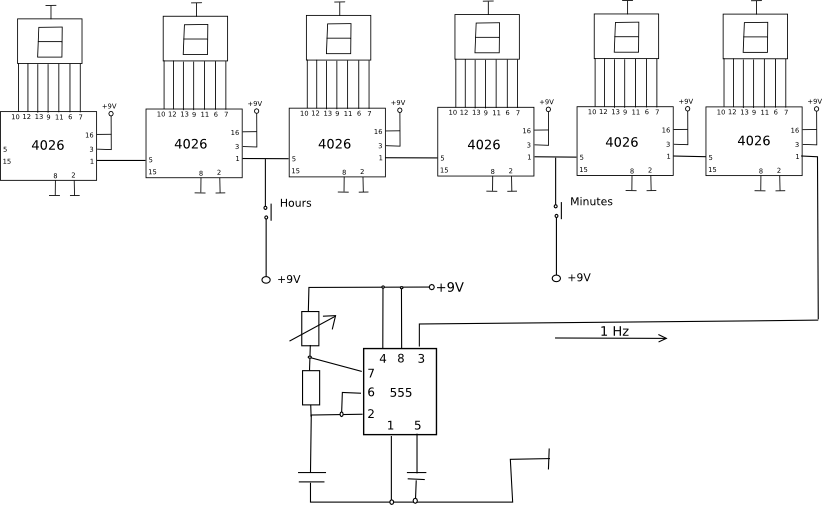 A practical digital clock using counters and decoders. (Image: Radek Crlík, Public domain, via Wikimedia Commons)
Based on the TU BIM syllabus for Digital Logic (IT233), unit 7.
Discussion
Loading…