Microprocessor and Computer ArchitectureUnit 29 min read
Microprocessor Architecture: Internal Structure, Registers, ALU, Control Unit
Unit 2 of Microprocessor and Computer Architecture explores the internal organization of microprocessors, covering the roles of registers, the Arithmetic Logic Unit (ALU), Control Unit (CU), and data paths. It explains how these components interact to execute instructions, with comparisons of Harvard vs. Von Neumann ar
Core Components of a Microprocessor
1. Registers: The Brain’s Short-Term Memory
Microprocessors use registers—tiny, ultra-fast storage locations inside the CPU—to hold data and instructions temporarily. They are classified based on their function:
classDiagram
    class Register {
        <<abstract>>
        +size: bits
        +name: String
    }
    class GeneralPurposeRegister {
        +store data/temporary results
    }
    class SpecialPurposeRegister {
        +hold flags, program counters, stack pointers
    }
    Register <|-- GeneralPurposeRegister
    Register <|-- SpecialPurposeRegister
Key Registers in x86 (Intel/AMD) and ARM Architectures:
| Register Type | Examples (x86) | Examples (ARM) | Purpose |
|---|---|---|---|
| General Purpose | AX, BX, CX, DX | R0-R15 | Store operands, intermediate results, and addresses. |
| Program Counter (PC) | EIP (32-bit), RIP (64-bit) | PC | Holds the address of the next instruction to execute. |
| Stack Pointer (SP) | ESP (32-bit), RSP (64-bit) | SP | Points to the top of the stack in memory. |
| Instruction Pointer (IP) | EIP | PC | Similar to PC but used in some contexts for instruction fetch. |
| Flag Register | EFLAGS (32-bit) | CPSR (Condition Flags) | Stores status flags (e.g., Zero Flag, Carry Flag) for conditional operations. |
Worked Example:
In an x86 microprocessor, if you execute MOV AX, 5, the value 5 is loaded into the AX (Accumulator) register. The ALU can then perform operations like ADD BX, AX, where the result is stored in BX.
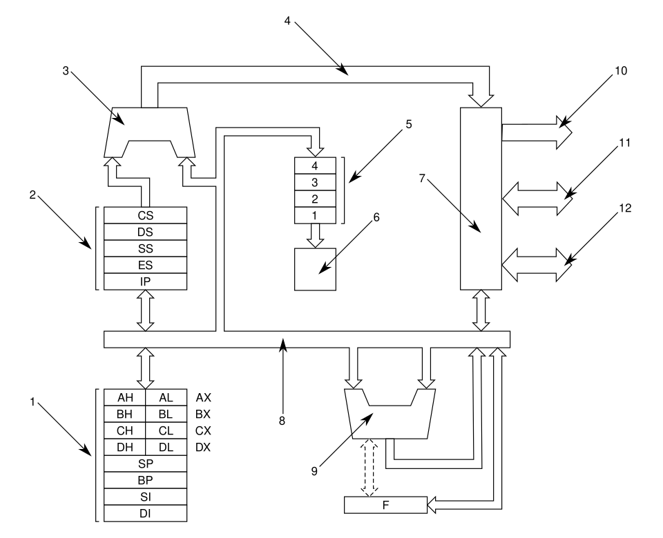 A labelled diagram of the 8086’s internal registers, ALU, and control unit. (Image: Harkonnen2, CC BY-SA 3.0, via Wikimedia Commons)
2. Arithmetic Logic Unit (ALU): The Math and Logic Engine
The ALU performs arithmetic (addition, subtraction, multiplication) and logical operations (AND, OR, NOT, XOR). It is the "workhorse" of the CPU, executing operations in a single clock cycle (in modern processors).
ALU Operations:
stateDiagram-v2
    [*] --> ALU_Idle
    ALU_Idle --> Perform_Arithmetic: on arithmetic instruction
    Perform_Arithmetic --> Check_Result: after operation
    Check_Result --> Set_Flags: update flags (e.g., Zero, Carry)
    Set_Flags --> ALU_Idle
    ALU_Idle --> Perform_Logical: on logical instruction
    Perform_Logical --> ALU_Idle
Example: Addition with Carry Flag
- Instruction:
ADD AL, BL(Add 8-bit registers AL and BL). - If the result exceeds 8 bits, the Carry Flag (CF) is set to
1. - This is used in multi-byte arithmetic (e.g., adding two 16-bit numbers by first adding the low bytes, then the high bytes with carry).
3. Control Unit (CU): The Traffic Cop
The Control Unit manages the execution of instructions by:
- Fetching instructions from memory.
- Decoding them into control signals.
- Coordinating data flow between registers, ALU, and memory.
CU Operations (Simplified):
sequenceDiagram
    participant CU as Control Unit
    participant PC as Program Counter
    participant IR as Instruction Register
    participant MU as Memory Unit
    CU->>PC: Fetch next instruction address
    PC-->>CU: Address
    CU->>MU: Read instruction at [Address]
    MU-->>IR: Instruction
    CU->>IR: Decode instruction
    IR-->>CU: Opcode and operands
    CU->>ALU: Send control signals (e.g., "ADD")
    ALU-->>CU: Result
    CU->>PC: Increment PC
Hardware Implementation: Modern CUs use microprogramming or hardwired control to generate signals. For example:
- A
JMP(jump) instruction triggers the CU to load the target address into the PC instead of incrementing it.
Architectural Models: Von Neumann vs. Harvard
| Feature | Von Neumann Architecture | Harvard Architecture |
|---|---|---|
| Memory Organization | Single memory for data and instructions. | Separate memory for data and instructions. |
| Data Bus | Shared bus for both data and instructions. | Separate data and instruction buses. |
| Speed | Slower (bottleneck on shared bus). | Faster (parallel access to data and instructions). |
| Examples | Intel x86, ARM Cortex-M (some variants). | DSPs (Digital Signal Processors), 8051 microcontrollers. |
Real-World Example:
- 8051 Microcontroller (Harvard): Used in embedded systems like eSewa’s payment terminals for parallel processing of transactions and data.
- Intel Core i7 (Von Neumann): Used in Ncell’s servers for general-purpose computing where shared memory simplifies programming.
Data Path: How Instructions Flow
The data path is the network of connections between registers, ALU, and memory. It includes:
- Buses: Data bus (transfers data), Address bus (specifies memory location), Control bus (carries signals).
- Multiplexers: Select data sources (e.g., choosing between a register or memory for ALU input).
- Decoders: Convert instruction opcodes into control signals.
Simplified Data Path Diagram:
Worked Example: Load Instruction (MOV R1, [MEM])
- CU sends address from
PCto memory. - Memory returns data to a temporary register.
- Multiplexer selects data from the temp register and sends it to
R1. - PC is incremented to fetch the next instruction.
Performance Factors in Microprocessor Design
- Clock Speed: Measured in GHz (e.g., 3.5 GHz = 3.5 billion cycles/sec).
- Pipeline Depth: Modern CPUs use pipelining (Unit 6) to overlap instruction execution stages (fetch, decode, execute, memory, write-back).
- Parallelism: Multiple ALUs (e.g., Intel’s Hyper-Threading) or SIMD (Single Instruction Multiple Data) for vector operations.
Real-World Tie-In:
- Pathao’s Ride-Hailing App uses ARM Cortex-A processors (Harvard-like design) for fast parallel processing of GPS data and user requests.
- NTC’s Network Routers rely on x86 CPUs with deep pipelines to handle thousands of data packets per second.
Exam Tip
- Diagrams are Key: Always draw and label the internal block diagram of a microprocessor (registers, ALU, CU, buses) in exams. Examiners love clear visuals!
- Compare Architectures: Questions often ask to contrast Von Neumann vs. Harvard. Memorize the table above and one real-world example for each.
- Register Roles: Know the purpose of PC, SP, and flag registers (e.g., how the Carry Flag affects arithmetic operations).
- Data Path Traces: Practice tracing a simple instruction (e.g.,
ADD R1, R2) through the data path. Show every step: fetch, decode, execute, write-back. - Shortcuts for Marks:
- For ALU operations, mention flags (Zero, Carry, Overflow).
- For CU, highlight fetch-decode-execute cycle.
- For architectures, state speed vs. complexity trade-offs.
In the Real World
eSewa’s Payment System:
- Uses ARM Cortex-M microcontrollers (Harvard architecture) in POS terminals to process transactions in parallel. The separate data/instruction buses allow simultaneous handling of user input and payment validation, reducing latency.
Ncell’s 4G Base Stations:
- Deploy Intel Xeon processors (Von Neumann) for central processing. The shared memory simplifies managing large-scale data (e.g., call routing tables), while pipelining ensures high throughput for thousands of simultaneous connections.
Daraz’s Order Fulfillment Queue:
- Imagine Daraz’s backend uses a priority queue (like a microprocessor’s interrupt handling). High-priority orders (e.g., same-day delivery) are processed first, similar to how the CU prioritizes critical interrupts over regular instructions. The stack pointer (SP) analogy helps: SP decrements for urgent tasks (like a stack pushing high-priority items).
Khalti’s Fraud Detection:
- Khalti’s servers use x86 CPUs with deep pipelines to analyze transaction patterns in real-time. The ALU’s logical operations (e.g., XOR for checksums) detect anomalies, while the CU’s interrupt handling flags suspicious activities for review.
Why This Matters for Your Exam
Understanding these concepts helps you:
- Design efficient programs (e.g., minimizing register usage in assembly).
- Troubleshoot hardware issues (e.g., why a program crashes when overwriting the stack pointer).
- Compare processors for specific tasks (e.g., choosing a DSP for audio processing vs. a general-purpose CPU).
Based on the TU BIM syllabus for Microprocessor and Computer Architecture (IT236), unit 2.
Discussion
Loading…