Microprocessor And Computer ArchitectureUnit 99 min read
Input/Output Interfacing – Devices, Methods, and Protocols
Unit 9 of Microprocessor And Computer Architecture: covers I/O fundamentals, device types, interfacing techniques, bus architectures, I/O addressing, and communication protocols such as UART, SPI, I2C, and DMA.
Key points
- I/O devices are classified as peripheral, storage, and communication devices, each requiring specific interfacing methods.
- Port‑mapped and memory‑mapped I/O provide two distinct ways to address peripheral registers.
- Polling, interrupt, and DMA are three I/O transfer modes, each with trade‑offs in CPU usage and throughput.
- Serial protocols (UART, SPI, I²C) differ in speed, complexity, and wiring, influencing system design choices.
- Understanding bus architectures and I/O addressing is essential for designing efficient embedded systems.
1. Introduction to I/O Interfacing
Input/Output (I/O) interfacing is the bridge between a microprocessor and the external world. It allows the processor to read data from sensors, display information, and control actuators. I/O devices are grouped into:
| Category | Examples | Typical Interface | Typical Use |
|---|---|---|---|
| Peripheral | Keyboard, mouse, display, sensor | Parallel, serial, USB | Human‑machine interaction |
| Storage | Flash, HDD, SSD | SATA, NVMe, SD | Data persistence |
| Communication | Network cards, modems | Ethernet, Wi‑Fi, Bluetooth | Data exchange |
The microprocessor accesses I/O devices through I/O buses that connect the CPU, memory, and peripheral controllers.
1.1 I/O Bus Architecture
A typical system bus consists of:
- Data bus (bidirectional)
- Address bus (unidirectional)
- Control bus (signals such as READ, WRITE, I/O, MEM)
The CPU issues an address and control signals; the peripheral decodes the address and responds on the data bus.
2. I/O Addressing: Port‑Mapped vs Memory‑Mapped
The microprocessor can access peripheral registers in two ways:
| Feature | Port‑Mapped I/O | Memory‑Mapped I/O |
|---|---|---|
| Address Space | Separate 16‑bit port address space | Uses normal memory address space |
| Instruction Set | Special IN/OUT instructions (x86) | Standard load/store instructions |
| Speed | Slightly faster due to dedicated bus | Slightly slower due to memory arbitration |
| Flexibility | Limited to 256 ports (x86) | Unlimited addresses |
| Use Case | Legacy PCs, simple microcontrollers | Modern microcontrollers, embedded systems |
2.1 Port‑Mapped I/O Example
On an x86 CPU, the keyboard controller is accessed via port 0x60.
flowchart TD
  A["CPU"] --> B["Issue OUT 0x60, data"]
  B --> C["Keyboard controller"]
  C --> D["Store data in buffer"]
2.2 Memory‑Mapped I/O Example
An ARM Cortex‑M microcontroller maps the UART peripheral at address 0x4000_0000.
flowchart TD
  A["CPU"] --> B["Load from 0x40000000"]
  B --> C["UART data register"]
  C --> D["Read byte"]
3. I/O Transfer Modes
I/O operations can be performed in three modes, each affecting CPU utilization and data throughput.
| Mode | Mechanism | CPU Usage | Throughput | Typical Use |
|---|---|---|---|---|
| Polling | CPU repeatedly checks device status | High | Low | Simple devices, low data rates |
| Interrupt | Device signals CPU when ready | Medium | Medium | Serial ports, keyboards |
| DMA | Dedicated DMA controller moves data | Low | High | Video memory, high‑speed peripherals |
3.1 Polling Example
Reading a byte from a UART via polling:
while (!(UART_STATUS & RX_READY)) ;   // Wait for data
uint8_t data = UART_DATA;             // Read byte
3.2 Interrupt Example
UART interrupt service routine (ISR):
void UART_ISR(void) {
    uint8_t data = UART_DATA;          // Read byte
    buffer[head++] = data;             // Store in circular buffer
}
sequenceDiagram
  participant CPU
  participant UART
  participant ISR
  CPU->>UART: Write data to transmit register
  UART->>CPU: Raise interrupt flag
  CPU->>ISR: Call UART_ISR
  ISR->>UART: Read received data
  ISR->>CPU: Return from interrupt
3.3 DMA Example
Transferring a 1 KB block from memory to an SPI peripheral:
DMA_Config.src = &mem[0];
DMA_Config.dst = &SPI_DATA;
DMA_Config.size = 1024;
DMA_Start(&DMA_Config);
stateDiagram-v2
  [*] --> Idle
  Idle --> DMA_Transfer : Start DMA
  DMA_Transfer --> DMA_Complete : Transfer done
  DMA_Complete --> Idle
4. Serial Communication Protocols
Serial protocols transmit data bit‑by‑bit over a single line or pair of lines. They are widely used in embedded systems due to their simplicity and low pin count.
4.1 UART (Universal Asynchronous Receiver/Transmitter)
UART uses start, data, parity, and stop bits. It is asynchronous, meaning no clock line is shared.
Worked Example – UART Transmission
A microcontroller sends byte 0xA5 (binary 10100101) with 1 stop bit and no parity.
| Bit | Value | Description |
|---|---|---|
| 0 | 0 | Start bit |
| 1-8 | 1 0 1 0 0 1 0 1 | Data bits (LSB first) |
| 9 | 1 | Stop bit |
The waveform shows a low start bit, data bits, and a high stop bit.
4.2 SPI (Serial Peripheral Interface)
SPI is synchronous, using a master clock. It requires four lines: SCLK, MOSI, MISO, SS.
Worked Example – SPI Transfer
Master sends byte 0x3C to a slave. Clock polarity CPOL=0, phase CPHA=0.
| Clock Edge | MOSI | MISO (slave response) |
|---|---|---|
| 1st rising | 0 | 1 |
| 2nd rising | 1 | 0 |
| 3rd rising | 1 | 1 |
| 4th rising | 0 | 0 |
| 5th rising | 0 | 1 |
| 6th rising | 1 | 0 |
| 7th rising | 1 | 1 |
| 8th rising | 0 | 0 |
flowchart LR
  A["Master"] --> B["Generate SCLK"]
  B --> C["MOSI: Send 0x3C"]
  C --> D["MISO: Receive 0xA5"]
  D --> E["Slave ACK"]
4.3 I²C (Inter‑Integrated Circuit)
I²C uses two lines: SDA (data) and SCL (clock). It supports multiple masters and slaves.
Worked Example – I²C Read
Master reads a byte from a temperature sensor at address 0x48.
- Master sends start condition.
- Master transmits
0x48 << 1 | 0(write). - Sensor ACKs.
- Master sends register address
0x00. - Sensor ACKs.
- Master sends repeated start.
- Master transmits
0x48 << 1 | 1(read). - Sensor ACKs.
- Sensor sends data byte
0x5A. - Master ACKs.
- Master sends stop condition.
sequenceDiagram
  participant Master
  participant Sensor
  Master->>Sensor: Start + Addr+Write
  Sensor->>Master: ACK
  Master->>Sensor: Register Addr
  Sensor->>Master: ACK
  Master->>Sensor: Repeated Start + Addr+Read
  Sensor->>Master: ACK
  Sensor->>Master: Data 0x5A
  Master->>Sensor: ACK
  Master->>Sensor: Stop
5. Direct Memory Access (DMA)
DMA allows peripherals to transfer data directly to/from memory without CPU intervention, freeing CPU cycles for other tasks.
5.1 DMA Controller Architecture
A DMA controller has:
- Channel: independent transfer path
- Descriptor: source, destination, size, control flags
- Interrupt: signals transfer completion
classDiagram
class DMA_Controller {
  +Channel[] channels
  +startTransfer(channel)
  +interruptHandler()
}
class Channel {
  +srcAddr
  +dstAddr
  +size
  +controlFlags
}
5.2 DMA Transfer Example
Transferring a 512‑byte image from SDRAM to an LCD controller:
- CPU writes descriptor to DMA channel 2.
- CPU enables channel 2.
- DMA controller reads descriptor, initiates transfer.
- DMA moves data block by block.
- On completion, DMA raises interrupt.
- CPU clears interrupt and continues processing.
stateDiagram-v2
  [*] --> Setup : CPU writes descriptor
  Setup --> Enable : CPU enables channel
  Enable --> Transfer : DMA starts transfer
  Transfer --> Complete : DMA finishes transfer
  Complete --> [*]
6. Parallel I/O
Parallel interfaces transmit multiple bits simultaneously, typically using a 8‑bit or 16‑bit data bus.
6.1 Parallel Port (LPT)
A classic parallel port uses 8 data lines, 2 control lines, and 5 status lines. It is used for printers and legacy devices.
flowchart TD
  A["CPU"] --> B["Write to LPT data port"]
  B --> C["Printer receives 8‑bit data"]
  C --> D["Printer processes data"]
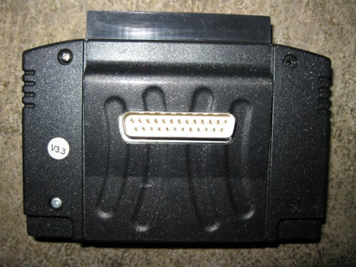 Parallel port connector on a PC (Image: InterActiveMania, CC BY-SA 4.0, via Wikimedia Commons)
6.2 Parallel Memory‑Mapped I/O
Some microcontrollers expose parallel ports via memory addresses, allowing simultaneous data transfer.
uint8_t *port = (uint8_t *)0x40001000;
*port = 0xFF;   // Write 8 bits to peripheral
7. I/O in Embedded Systems – Case Study
Consider a smart meter that reads electricity consumption and sends data to a central server.
- Sensor Interface: Current transformer outputs analog voltage → ADC (memory‑mapped).
- Data Processing: CPU calculates consumption.
- Communication: UART sends data to GSM module (interrupt mode).
- Power Management: DMA transfers data from ADC buffer to UART to reduce CPU load.
This architecture demonstrates the synergy of memory‑mapped I/O, interrupts, and DMA.
8. Comparison Table – I/O Transfer Methods
| Feature | Polling | Interrupt | DMA |
|---|---|---|---|
| CPU involvement | Continuous | Event‑driven | Minimal |
| Latency | High | Medium | Low |
| Throughput | Low | Medium | High |
| Complexity | Low | Medium | High |
| Power consumption | High | Medium | Low |
9. In the real world
- eSewa payment terminal: Uses UART to communicate with the microcontroller that processes card data. The terminal’s firmware reads card data via UART interrupt and sends transaction details over Wi‑Fi (SPI‑based Wi‑Fi module).
- Ncell SIM card reader: The SIM card interface uses ISO‑7816 (a variant of UART) over a serial bus. The microcontroller polls the SIM for ATR (Answer To Reset) and then uses interrupts for data exchange.
- Daraz warehouse robots: Employ SPI to control motor drivers and I²C to read position sensors. DMA is used to stream video from a camera to the robot’s onboard computer for obstacle detection.
10. Exam tip
- Understand the difference between port‑mapped and memory‑mapped I/O.
- Know the steps of UART, SPI, and I²C frame formats.
- Be able to draw a simple DMA transfer diagram and explain its advantage.
- Practice tracing a polling, interrupt, and DMA sequence for a peripheral.
- Review the comparison table of I/O transfer modes and be ready to justify a choice for a given application.
Based on the TU BITM syllabus for Microprocessor And Computer Architecture (IT236), unit 9.
Discussion
Loading…