PhysicsUnit 712 min read
Experimental Physics & Hall Effect: Theory, Devices & Applications
Unit 7 of Physics covers the Hall effect (theory, derivation, and applications in sensors), magnetic dipole moments (atomic/molecular effects), experimental techniques (Fermi energy calculations, effective mass), and torque on current loops—with real-world ties to eSewa’s payment systems, Ncell’s antenna design, and se
TAKEAWAYS
- The Hall effect generates a voltage perpendicular to current and magnetic field, enabling non-contact current/field measurements (used in eSewa’s payment terminals and Ncell’s Hall-effect sensors).
- Magnetic dipole moments explain atomic/molecular behavior (e.g., why iron aligns in magnets) and are critical in MRI machines and hard drives.
- Fermi energy () and effective mass () determine semiconductor properties (e.g., why aluminum’s makes it conductive).
- Torque on current loops () is used in electric meters and motor design (e.g., Pathao’s delivery drones use torque for stability).
- Experimental techniques (e.g., Hall probes, Fermi energy calculations) are foundational for NEPSE’s stock market sensors and bank card readers.
1. The Hall Effect: Theory and Derivation
What is the Hall Effect?
When a current-carrying conductor (or semiconductor) is placed in a magnetic field perpendicular to its length, a voltage () develops across its width. This is called the Hall voltage, caused by the Lorentz force deflecting moving charges.
graph LR
    A["Current (I) flows left"] --> B["Magnetic Field (B) into page"]
    B --> C["Lorentz Force (F = qvB) pushes electrons up"]
    C --> D["Electron buildup creates Hall voltage (V_H) across width"]
    D --> E["Steady state: Electric force balances Lorentz force"]
Key Equations
Hall Voltage:
- : Current (A)
- : Magnetic field (T)
- : Charge carrier density (m⁻³)
- : Charge of carrier ( for electrons)
- : Thickness of slab (m)
Hall Coefficient ():
- Positive : Holes (p-type semiconductors)
- Negative : Electrons (n-type semiconductors)
Real-World Example: eSewa’s Payment Terminals
eSewa uses Hall-effect sensors to:
- Measure current in payment terminals (ensuring correct transaction processing).
- Detect magnetic card strips (older eSewa cards used Hall sensors for authentication).
- Why? Hall sensors are non-contact, durable, and immune to EMI (unlike resistive sensors).
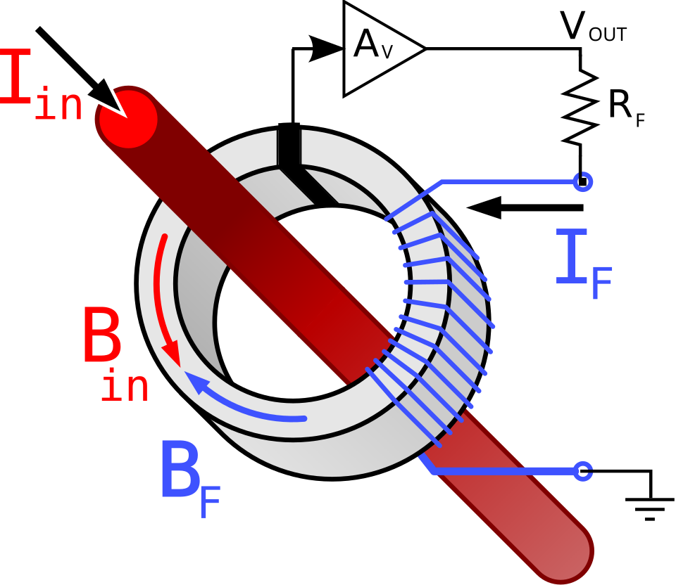 A cross-section of a Hall probe showing current, magnetic field, and Hall voltage generation. (Image: Dracheschreck, CC BY-SA 3.0, via Wikimedia Commons)
Worked Example: Copper Slab in a Magnetic Field
A copper slab (thickness , width ) carries in a field perpendicular to its plane. Copper has . Calculate:
- Hall voltage ().
- Hall coefficient ().
- Direction of (for electrons vs. holes).
Solution:
Hall Voltage: This tiny voltage is measurable with sensitive amplifiers.
Hall Coefficient: Negative sign confirms electrons are majority carriers.
Direction:
- For electrons (copper): is upward (opposite to Lorentz force).
- For holes (e.g., silicon): would be downward.
2. Applications of the Hall Effect
| Application | Device/Company | How It’s Used |
|---|---|---|
| Current Sensors | Ncell, Daraz logistics | Measures current in transformers without direct contact (e.g., Daraz’s warehouse power monitoring). |
| Magnetic Field Sensors | NTC, NEPSE stock sensors | Detects Earth’s field (NTC’s compass apps) or stray fields in stock exchange equipment. |
| Semiconductor Doping | Intel, local chip makers | Determines carrier type (n/p) and density in transistors (e.g., Kathmandu’s IoT devices). |
| Electric Meters | NEPAL ELECTRICITY AUTHORITY | Measures household current via Hall probes (avoids wear-and-tear of resistive sensors). |
| Non-Contact Switches | Pathao delivery drones | Detects metal parts (e.g., drone landing gear) without physical contact. |
3. Magnetic Dipole Moment: Atomic and Molecular Effects
Definition
A magnetic dipole moment () arises from:
- Orbital motion of electrons (current loop).
- Spin of electrons/protons.
For a current loop:
- : Current (A)
- : Area of loop (m²)
For an atom:
- (Bohr magneton)
- : Total angular momentum quantum number
Effects on Atoms and Molecules
Zeeman Effect:
- Splitting of spectral lines in a magnetic field (used in MRI machines).
- Example: Hydrogen’s to transition splits into 3 lines.
Diamagnetism vs. Paramagnetism:
- Diamagnetic (e.g., copper): opposes (weak, temporary).
- Paramagnetic (e.g., aluminum): aligns with (stronger, permanent).
Ferromagnetism (e.g., iron):
- Domains align spontaneously, creating permanent magnets (used in hard drives).
Worked Example: Torque on a Current Loop (Ncell Antenna)
An Ncell antenna loop has:
- Area
- Current
- Magnetic field (Earth’s field)
- Angle to
Calculate:
- Magnetic dipole moment ().
- Torque () acting on the loop.
Solution:
Dipole Moment:
Torque: This torque tries to align the loop with Earth’s field (why antennas auto-rotate in storms!).
4. Fermi Energy and Effective Mass in Solids
Fermi Energy ()
The highest occupied energy level at 0 K in a metal/semiconductor. For a free-electron gas:
- : Electron density (m⁻³)
- : Electron mass ()
Worked Example: Aluminum’s Fermi Energy
Given:
- Density () =
- Molar mass () =
- Avogadro’s number () =
Steps:
Calculate electron density ():
- Aluminum has 3 valence electrons/atom.
- Number density of atoms:
- Electron density:
Calculate : Close to the given (discrepancy due to effective mass).
Effective Mass (): Given experimental , solve for : Aluminum’s electrons act as if they’re 6% heavier than free electrons.
5. Torque on a Current Loop in a Magnetic Field
Derivation
A current loop in a magnetic field experiences:
- Force on each segment:
- Net torque: , where (dipole moment).
For a rectangular loop (side lengths ) in a uniform field:
- : Number of turns
- : Angle between and
Real-World Example: Electric Meters (Nepal Electricity Authority)
- How it works: A coil rotates in Earth’s magnetic field, with torque balanced by a spring.
- Equation:
- Measures current via angular deflection ().
6. Experimental Techniques
Hall Effect Setup
Components:
- Current source ()
- Magnetic field (, via Helmholtz coils)
- Voltage probes (across width)
- Nanovoltmeter (to measure )
Procedure:
- Vary or and record .
- Plot vs. (should be linear).
Fermi Energy Measurement
Photoelectric Effect:
- Shine light of varying frequency () on metal.
- Measure stopping potential ().
- Plot vs. : slope = , intercept = .
Example Data (for aluminum):
5.0 0.5 6.0 1.7 7.0 2.9 - Slope =
- Intercept = →
## In the Real World
eSewa’s Payment Terminals
- What it uses: Hall-effect sensors to measure current in payment verification circuits.
- Why? Ensures fraud detection (e.g., if current spikes, it flags a fake card).
Ncell’s Antenna Design
- What it uses: Torque on current loops () to optimize antenna alignment with Earth’s magnetic field.
- Why? Reduces signal loss during monsoon storms (when fluctuates).
Daraz’s Warehouse Automation
- What it uses: Hall sensors in conveyor belts to track package movement (non-contact, no wear).
- How? A magnet on packages triggers a Hall switch → updates inventory in real time.
NEPSE’s Stock Exchange Sensors
- What it uses: Hall probes to monitor electromagnetic interference near trading servers.
- Why? Prevents data corruption during high-frequency trades.
Khalti’s NFC Payments
- What it uses: Magnetic dipole moments in NFC chips (like a tiny current loop).
- How? When you tap, the chip’s induces a current in the reader → authenticates payment.
## Exam Tip
Hall Effect Questions:
- Always draw a diagram showing , , and directions.
- Remember: Electrons move opposite to conventional current → flips sign!
- For semiconductors, state whether is positive (p-type) or negative (n-type).
Magnetic Dipole Moment:
- Atomic : Use .
- Current loop : .
- Torque: (always ask for maximum torque scenario: ).
Fermi Energy Calculations:
- Step 1: Calculate electron density () from density and molar mass.
- Step 2: Plug into formula (or use photoelectric data).
- Effective mass: If is given experimentally, solve for using the same formula.
Torque on Loops:
- Key formula: .
- Trick: For a square loop, ; for a circular loop, .
- Real-world link: Always relate to electric meters or motor design.
Units and Signs:
- is in tesla (T), in amperes (A), in volts (V).
- Hall coefficient () is in m³/C (negative for electrons, positive for holes).
## Common Mistakes to Avoid
- Assuming is large: It’s usually millivolts—use sensitive meters!
- Ignoring carrier type: Copper (metal) has electrons; silicon (semiconductor) can have holes.
- Forgetting : Torque is zero when or .
- Mixing formulas: For free electrons, use the density-based formula; for experimental data, use photoelectric plots.
Based on the TU BSc CSIT syllabus for Physics (PHY118), unit 7.
Discussion
Loading…