MicroprocessorUnit 415 min read
8086 Architecture, Instructions & Programming: Segments, Registers, and Real Mode
Unit 4 of Microprocessor covers the 8086’s 16-bit architecture, segmented memory model, register organization, instruction set (data transfer, arithmetic, logic, control), and programming basics—with real-world ties to embedded systems, DOS-era apps, and modern x86 compatibility.
TAKEAWAYS:
- The 8086 uses a segmented memory model (CS:IP, DS:SI/DI, SS:SP) to address 1 MB of memory via 16-bit registers and 20-bit physical addresses.
- Registers are divided into general-purpose (AX, BX, CX, DX), pointer/index (SP, BP, SI, DI), and segment (CS, DS, SS, ES) registers, each with specific roles in addressing and operations.
- Instructions are classified into 5 groups: data transfer, arithmetic, logic, control transfer, and string operations, with prefixes (e.g.,
REP,LOCK) for advanced use. - The instruction cycle involves fetching (M-cycle) and executing (T-states) instructions, with the 8086 using a 4-phase bus cycle (T1–T4) for memory/I/O access.
- Real Mode (vs. Protected Mode) allows direct memory access but lacks hardware protection, used in legacy DOS and bootloaders.
- Programming examples include stack operations (
PUSH/POP), loop control (LOOP), and segmented addressing (e.g., loading data from[BX+SI]).
1. Architecture Overview: The 8086’s Core Design
The 8086 is an intel 16-bit microprocessor introduced in 1978, designed for personal computers. It introduced key innovations like segmented memory and a 16-bit ALU, laying the foundation for modern x86 processors. Unlike the 8085 (8-bit), the 8086 uses a 16-bit data bus and 20-bit address bus, allowing it to access 1 MB of memory (2²⁰ bytes).
Key Features:
- 16-bit internal architecture but 20-bit external address bus (via multiplexing).
- Two 8-bit ALUs working in parallel for efficiency.
- 14 general-purpose registers (8-bit and 16-bit variants).
- Segmented memory model (CS, DS, SS, ES registers).
- Interrupt-driven I/O (via IN/OUT instructions or DMA).
Why Segmented Memory?
The 8086’s 16-bit registers cannot directly address 1 MB (2²⁰ bytes). Instead, it uses segment registers (CS, DS, SS, ES) to define 16-bit base addresses, combined with 16-bit offsets (e.g., BX, SI) to compute a 20-bit physical address:
Physical Address = (Segment Register × 16) + Offset
Example: If CS = 1000H and IP = 0100H, the physical address is:
1000H × 16 = 10000H
10000H + 0100H = 10100H (40 KB)
classDiagram
    class Registers {
        +AX, BX, CX, DX (16-bit)
        +AH, AL, BH, BL, etc. (8-bit halves)
        +SP, BP, SI, DI (Pointer/Index)
        +CS, DS, SS, ES (Segment)
        +IP (Instruction Pointer)
        +FLAGS (Status Register)
    }
    class Memory {
        +CS:IP (Code Segment)
        +DS:SI/DI (Data Segment)
        +SS:SP (Stack Segment)
        +ES (Extra Segment)
    }
    Registers --> Memory : "Addresses via Seg:Offset"
Caption: 8086 Register Organization and Segmented Memory Model
2. Registers: The 8086’s Workhorses
The 8086 has 14 registers, categorized as follows:
| Type | Registers | Purpose |
|---|---|---|
| General-Purpose | AX, BX, CX, DX | Accumulator (AX), Base (BX), Counter (CX), Data (DX) |
| Pointer/Index | SP, BP, SI, DI | Stack Pointer (SP), Base Pointer (BP), Source/Index (SI/DI) |
| Segment | CS, DS, SS, ES | Code Segment (CS), Data Segment (DS), Stack Segment (SS), Extra Segment (ES) |
| Special | IP, FLAGS | Instruction Pointer (IP), Status Flags (FLAGS) |
Key Registers Explained:
AX (Accumulator):
- Used in arithmetic/logic operations (e.g.,
ADD AX, BX). - Can be split into
AH(high byte) andAL(low byte). - Example:
MOV AL, 32Hloads32Hinto the low byte of AX.
- Used in arithmetic/logic operations (e.g.,
IP (Instruction Pointer):
- Points to the next instruction in the Code Segment (CS).
- Automatically increments after each instruction fetch.
FLAGS Register:
- 16-bit register storing status flags (e.g.,
CFfor Carry,ZFfor Zero,SFfor Sign). - Used for conditional jumps (e.g.,
JZjumps ifZF=1).
- 16-bit register storing status flags (e.g.,
Stack Pointer (SP) and Base Pointer (BP):
SPtracks the top of the stack in the Stack Segment (SS).BPis used for accessing local variables in functions (e.g.,[BP+2]).
REAL WORLD:
eSewa App (Nepal): When you pay a bill via eSewa, the backend server (often running on x86 processors) uses segmented memory to manage multiple user transactions simultaneously. The
DSregister might point to a segment storing user data, whileCSpoints to the code handling payments. The stack (SS:SP) is used to save return addresses for nested function calls (e.g., validation → payment processing → confirmation).Khalti’s Payment Gateway: Khalti’s servers use 8086-like segmented addressing (in modern x86-64 mode) to isolate different services (authentication, transaction logging, fraud detection). The
ESsegment might hold encrypted transaction data, whileDSholds decrypted user inputs.Pathao’s Ride Allocation: Pathao’s backend uses bitwise logic operations (e.g.,
AND,OR) to manage driver availability flags. For example:MOV AL, [DriverStatus] ; Load driver's status (bitmask) AND AL, 00000010B ; Check if driver is "available" (bit 1 set) JZ NotAvailable ; Jump if zero (not available)
3. Instruction Set: The 8086’s Command Language
The 8086 instruction set is divided into 5 categories:
A. Data Transfer Instructions
Move data between registers, memory, and I/O.
MOV: Move data (e.g.,MOV AX, BX).PUSH/POP: Stack operations (e.g.,PUSH AXsaves AX to stack;POP BXrestores to BX).XCHG: Exchange registers (e.g.,XCHG AX, BX).LEA: Load Effective Address (e.g.,LEA BX, [SI+DI]).
Example: Stack Operations
MOV AX, 1234H    ; Load AX with 1234H
PUSH AX          ; Push AX onto stack (SS:SP decremented by 2)
POP BX           ; Pop from stack into BX
Trace:
- Before
PUSH AX:SP = 0FFEH,[SS:0FFE] = ?,[SS:0FFF] = ? - After
PUSH AX:SP = 0FFCH,[SS:0FFCH] = 34H,[SS:0FFDH] = 12H - After
POP BX:BX = 1234H,SP = 0FFEH
sequenceDiagram
    participant CPU
    participant Stack
    CPU->>Stack: PUSH AX (SP--; [SS:SP] = AX)
    Stack-->>CPU: Stack grows downward
    CPU->>Stack: POP BX (BX = [SS:SP]; SP++)
Caption: Stack Operations in 8086 (PUSH/POP)
B. Arithmetic Instructions
Perform math operations.
ADD,SUB,INC,DEC: Basic arithmetic.MUL,DIV,IMUL,IDIV: Multiplication/division (unsigned/signed).CMP: Compare two values (sets flags).
Example: Loan Interest Calculation (Nepal Bank Scenario) A bank calculates monthly interest on a loan using the formula:
Interest = Principal × Rate × Time / 100
In 8086 assembly:
MOV AX, Principal   ; AX = 100000 (1 lakh)
MOV BX, 10          ; BX = 10% rate
MUL BX              ; AX = AX × BX = 1000000 (overflows!)
; Use 32-bit multiplication (DX:AX)
MOV AX, Principal
MOV BX, Rate
MOV CX, Time
IMUL BX             ; AX = AX × BX (signed)
IMUL CX             ; DX:AX = AX × CX
MOV BX, 100
IDIV BX             ; AX = (DX:AX) / 100 (quotient)
Note: The 8086 lacks native 32-bit ops, so we use DX:AX for large numbers.
C. Logic Instructions
Bitwise operations.
AND,OR,XOR,NOT: Logical operations.TEST: CombineANDwithCMP(sets flags but discards result).
Example: Daraz Order Status Flags Daraz might use bitmask flags to track order status:
MOV AL, OrderStatus ; AL = 00001101B (Paid + Shipped)
AND AL, 00000010B   ; Check if "Shipped" bit (bit 1) is set
JZ NotShipped       ; Jump if not shipped
Flags:
- Bit 0:
00000001B= Paid - Bit 1:
00000010B= Shipped - Bit 2:
00000100B= Delivered
D. Control Transfer Instructions
Change program flow.
JMP: Unconditional jump.CALL/RET: Function calls.LOOP: Loop control (e.g.,LOOP Labeldecrements CX and jumps if CX ≠ 0).- Conditional jumps:
JZ,JNZ,JC,JNC, etc.
Example: Traffic Light Control (Kathmandu Roads) A traffic light controller might use a loop to cycle through states:
MOV CX, 3          ; 3 states: Red, Yellow, Green
RedLight:
    ; Turn on red light
    LOOP GreenLight ; Decrement CX; jump if CX ≠ 0
GreenLight:
    ; Turn on green light
    JMP RedLight     ; Repeat
stateDiagram-v2
    [*] --> RedLight
    RedLight --> YellowLight : "After 30 sec"
    YellowLight --> GreenLight : "After 5 sec"
    GreenLight --> RedLight : "After 45 sec"
Caption: Traffic Light State Machine (8086 Assembly)
E. String Instructions
Process arrays/strings.
MOVSB,CMPSB,SCASB: Move, compare, scan bytes.- Prefixes:
REP: Repeat until CX=0 (e.g.,REP MOVSBcopies CX bytes).REPE/REPNE: Repeat while equal/not equal.
Example: Copying a String (eSewa User Data)
LEA SI, SourceString   ; SI = address of source
LEA DI, DestString     ; DI = address of destination
MOV CX, 20             ; Copy 20 bytes
CLD                    ; Clear direction flag (auto-increment SI/DI)
REP MOVSB              ; Repeat MOVSB CX times
4. Instruction Cycle and Timing
The 8086 executes instructions in machine cycles, each divided into T-states (clock cycles). A typical instruction cycle involves:
Fetch Cycle (M-cycle):
T1: Address sent on bus (multiplexed with AD0–AD7).T2: Memory/I/O responds with data.T3: Data latched into CPU.T4: Next cycle begins.
Execution Cycle (T-states):
- Decode and execute the instruction.
Example: Timing Diagram for MVI A, 32H (8085-style, but concept applies)
(Note: The 8086 uses a 4-phase bus cycle, but the 8085’s 5-phase cycle is often taught for comparison.)
Caption: Simplified 8086 Fetch Cycle (4-Phase Bus)
5. Real Mode vs. Protected Mode (Brief Introduction)
The 8086 operates in Real Mode, where:
- No memory protection: Any process can access any memory.
- 20-bit addressing: Limited to 1 MB.
- No privilege levels: All code runs at ring 0.
Later x86 processors (80286+) added Protected Mode, enabling:
- Memory segmentation with limits (prevents overwrites).
- Privilege levels (ring 0–3 for OS/kernel vs. apps).
- Virtual memory (paging).
Example: Why Real Mode is Used in Bootloaders When a PC boots, the BIOS loads the MBR (Master Boot Record) into memory and jumps to it in Real Mode because:
- The BIOS itself runs in Real Mode.
- Protected Mode requires enabling via
LGDTandLMSWinstructions, which are complex for early boot.
6. Programming Example: Factorial Calculation
Problem: Compute 5! (120) using 8086 assembly.
Approach: Use a loop with CX as counter and AX as accumulator.
MOV AX, 1          ; Initialize result (AX = 1)
MOV CX, 5          ; Compute 5!
FactorialLoop:
    MUL CX          ; AX = AX × CX
    LOOP FactorialLoop
Trace:
| Step | AX (Result) | CX (Counter) | Action |
|---|---|---|---|
| 1 | 1 | 5 | Start |
| 2 | 5 (1×5) | 4 | MUL 5; LOOP |
| 3 | 20 (5×4) | 3 | MUL 4; LOOP |
| 4 | 60 (20×3) | 2 | MUL 3; LOOP |
| 5 | 120 (60×2) | 1 | MUL 2; LOOP |
| 6 | 120 | 0 | LOOP ends (CX=0) |
REAL WORLD:
- NTC’s Billing System:
NTC’s billing software (running on legacy x86 servers) might use factorial-like loops to calculate complex tariffs (e.g., volume discounts). For example:
MOV AX, 1        ; Base unit cost
MOV CX, 100      ; 100 units purchased
MOV BX, 10       ; Discount threshold
CMP CX, BX
JL NoDiscount     ; Jump if CX < BX
; Apply 10% discount (multiply by 0.9)
MOV DX, 0        ; Clear upper 16 bits
MOV AX, 90       ; 90% of cost (AX = AX × 90/100)
IMUL CX          ; AX = AX × CX (total cost)
JMP EndCalc
NoDiscount:
    IMUL CX      ; AX = AX × CX (no discount)
EndCalc:
7. Common Pitfalls and Best Practices
Segment Overlap:
- Ensure segments do not overlap unintentionally (e.g.,
CSandDSpointing to the same memory). - Fix: Use
ORGdirectives in assemblers to define segment offsets.
- Ensure segments do not overlap unintentionally (e.g.,
Stack Overflow:
- The stack grows downward. If
SPunderflows (points to invalid memory), the program crashes. - Fix: Initialize
SPto a high memory address (e.g.,MOV SP, 0FFFFH).
- The stack grows downward. If
Flag Dependence:
- Instructions like
CMPset flags but discard results. Always check flags after comparisons. - Example:
CMP AX, BX      ; Sets flags but AX unchanged
JE Equal        ; Jump if AX == BX
- Instructions like
16-bit Limitations:
- The 8086 cannot directly address >1 MB. Use far jumps (
JMP FAR) for inter-segment jumps. - Example:
JMP FAR PTR NewSegment:NewOffset
- The 8086 cannot directly address >1 MB. Use far jumps (
In the Real World
WhatsApp (Signal Protocol):
- WhatsApp’s encryption uses bitwise XOR operations (similar to
XORin 8086) for symmetric key derivation. For example, when you send a message, the client and server perform:
This is analogous to:Key = SharedSecret XOR NonceMOV AL, SharedSecret XOR AL, Nonce
- WhatsApp’s encryption uses bitwise XOR operations (similar to
Google’s Data Centers (x86 Servers):
- Modern x86 servers (descendants of the 8086) use segmented addressing in legacy compatibility modes. For example:
- A web server might load HTML pages from
DS:SI(data segment) while executing code fromCS:IP. - The stack (SS:SP) is used for recursive function calls in handling thousands of HTTP requests.
- A web server might load HTML pages from
- Modern x86 servers (descendants of the 8086) use segmented addressing in legacy compatibility modes. For example:
Nepal Rastra Bank’s Core Banking System:
- The bank’s mainframe uses 8086-style assembly (or emulated environments) for critical transactions like:
- Loan amortization schedules (using
LOOPand arithmetic ops). - Fraud detection (bitmask checks with
AND/TEST). - Audit logs (stack-based function call tracking).
- Loan amortization schedules (using
- The bank’s mainframe uses 8086-style assembly (or emulated environments) for critical transactions like:
Exam Tip
Draw the Block Diagram:
- Always draw the 8086’s internal architecture (EU, BU, BIU) and register organization in exams. Label:
- EU (Execution Unit): ALU, FLAGS, general registers.
- BU (Bus Unit): Address multiplexer, data bus.
- BIU (Bus Interface Unit): Instruction queue, segment registers.
- Always draw the 8086’s internal architecture (EU, BU, BIU) and register organization in exams. Label:
Segmented Addressing is Key:
- Questions often ask for physical address calculations. Practice:
Given: CS = 2000H, IP = 0050H → Physical Address = ?
Answer: 2000H × 16 = 20000H; 20000H + 0050H = 20050H
- Questions often ask for physical address calculations. Practice:
Instruction Cycle vs. Machine Cycle:
- Instruction Cycle: Time to fetch and execute one instruction.
- Machine Cycle: One bus operation (e.g., memory read/write). An instruction may require multiple machine cycles.
PUSH/POP and Stack:
PUSHdecrementsSPby 2 (for 16-bit data) before storing.POPreads from[SS:SP]and incrementsSPby 2.- Example Question:
"If SP = 0FFEH before
PUSH AXand AX = 1234H, what is[SS:0FFCH]after the push?" Answer:34H(low byte of AX).
Real Mode vs. Protected Mode:
- Real Mode: No protection, 1 MB limit (used in DOS, bootloaders).
- Protected Mode: Segmentation with limits, privilege levels (used in OS kernels).
- Exam Trick: The 80286 introduced Protected Mode; the 8086 only has Real Mode.
Common Exam Questions:
- Trace an instruction (e.g.,
MOV AX, [BX+SI]). - Explain the role of
CS:IP(code segment and instruction pointer). - Difference between
JMPandCALL(CALLpushes return address;JMPdoes not). - Why is the 8086 address bus multiplexed? Answer: To reduce pin count (AD0–AD7 are reused for data).
- Trace an instruction (e.g.,
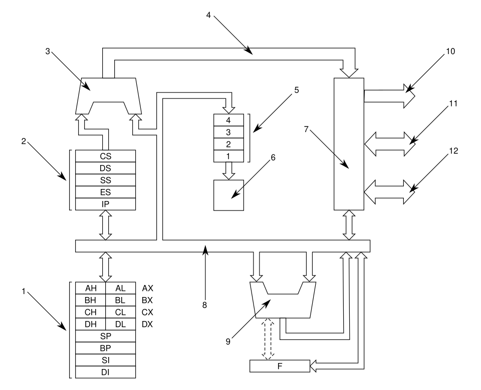 Internal architecture of the 8086 showing EU, BU, and BIU (Image: Harkonnen2, CC BY-SA 3.0, via Wikimedia Commons)
Based on the TU BSc CSIT syllabus for Microprocessor (CSC167), unit 4.
Discussion
Loading…