Computer Hardware DesignUnit 214 min read
Instructions: Machine Language, Formats & Execution
Unit 2 of Computer Hardware Design explores how computers execute instructions through machine language, instruction formats, addressing modes, and the fetch-decode-execute cycle. It covers instruction set architecture (ISA), assembly language, and how low-level programming interacts with hardware.
TAKEAWAYS:
- Instructions are the fundamental commands a CPU executes, encoded in binary (machine language) or assembly (human-readable).
- Instruction formats define how operands, opcode, and addressing modes are structured (e.g., 3-address, 2-address, 1-address).
- Addressing modes determine how operands are specified (e.g., immediate, direct, indirect, indexed).
- The fetch-decode-execute cycle is the core process of instruction execution, involving the program counter (PC), instruction register (IR), and control unit.
- Assembly language provides a mnemonic representation of machine instructions, aiding human readability while translating to binary.
- Real-world applications include compilers (translating high-level code to machine instructions), embedded systems (direct hardware control), and operating systems (managing instruction execution).
1. Introduction to Instructions
Computers execute programs through a sequence of instructions, which are binary-encoded commands. These instructions are stored in memory and fetched one by one for execution. The Instruction Set Architecture (ISA) defines the set of instructions a CPU can execute, including:
- Machine Language: Binary representation of instructions (e.g.,
10110000forADDin some ISAs). - Assembly Language: Human-readable mnemonics (e.g.,
ADD R1, R2, R3) that map to machine code. - High-Level Language: Languages like C or Python, which are compiled/interpreted into machine instructions.
Why Instructions Matter
- They bridge the gap between human-readable code and hardware execution.
- They define the capabilities of a CPU (e.g., arithmetic, logic, control flow).
- They determine efficiency (e.g., RISC vs. CISC architectures).
2. Instruction Formats
Instructions consist of:
- Opcode (Operation Code): Specifies the operation (e.g.,
ADD,SUB,JMP). - Operands: Data or memory addresses involved in the operation.
- Addressing Modes: Methods to specify operands (discussed later).
Common Instruction Formats
| Format Type | Example | Description |
|---|---|---|
| 3-Address | ADD R1, R2, R3 |
Three operands: two sources, one destination. |
| 2-Address | ADD R1, R2 |
Two operands; one is implicitly the destination (e.g., R1 = R1 + R2). |
| 1-Address | ADD R1 (with implicit accumulator) |
One operand; accumulator holds another value. |
| 0-Address | ADD (stack-based) |
Operands are popped from a stack; result is pushed back. |
| Variable-Length | CISC (e.g., x86) | Instructions vary in size (e.g., MOV AX, BX vs. ADD AL, BL). |
Example: MIPS Instruction Format (32-bit)
   31 26 25 21 20 16 15 11 10 6 5 0
   +-------------------+-------------------+
   |       opcode      |      rs           |
   +-------------------+-------------------+
   |       rt           |       rd           |
   +-------------------+-------------------+-------------------+
   |       shamt        |       funct        |
   +-------------------+-------------------+
- opcode: Specifies the instruction type (e.g.,
000000for R-type,001000forADD). - rs, rt, rd: Register operands.
- funct: Further specifies the operation (e.g.,
100000forADD).
3. Addressing Modes
Addressing modes determine how operands are accessed. Common modes include:
| Mode | Example (MIPS) | Description |
|---|---|---|
| Immediate | ADD R1, R2, #5 |
Operand is part of the instruction (e.g., #5 is a constant). |
| Register | ADD R1, R2, R3 |
Operands are registers. |
| Direct | ADD R1, R2, [R3] |
Operand is the memory address stored in a register. |
| Indirect | ADD R1, [R2] |
Operand is the memory address stored in the operand field. |
| Register Indirect | ADD R1, [R2] |
Operand is the memory address held in a register. |
| Indexed | ADD R1, [R2 + #4] |
Operand is base + offset (e.g., R2 + 4). |
| Base + Index | ADD R1, [R2 + R3] |
Operand is base + index (e.g., R2 + R3). |
| PC-Relative | BEQ R1, R2, label |
Operand is relative to the program counter (PC). |
Example: Loading a Value from Memory (Direct Addressing)
LW R1, 1000(R0) # Load word from memory address 1000 into R1
LW: Load word instruction.1000(R0): Memory address1000(withR0as base register, often zero).
4. The Fetch-Decode-Execute Cycle
The CPU executes instructions in a repeating cycle:
flowchart LR
    A["Program Counter (PC)"] -->|"Fetch"| B["Memory"]
    B -->|"Instruction"| C["Instruction Register (IR)"]
    C -->|"Decode"| D["Control Unit"]
    D -->|"Execute"| E["ALU/Registers/Memory"]
    E -->|"Update"| A
Steps:
- Fetch: The PC holds the address of the next instruction. The instruction is fetched from memory and stored in the Instruction Register (IR).
- Decode: The control unit decodes the opcode to determine the operation.
- Execute: The ALU or other units perform the operation (e.g., arithmetic, logic, or control flow).
- Update: The PC is updated to point to the next instruction (e.g., incremented or jumped to).
Example Trace: Executing ADD R1, R2, R3
| Step | Action |
|---|---|
| Fetch | PC = 1000 → Fetch ADD R1, R2, R3 from memory address 1000. |
| Decode | IR = ADD R1, R2, R3 → Control unit identifies ADD operation. |
| Execute | ALU computes R1 = R2 + R3. |
| Update | PC = 1004 (next instruction). |
5. Assembly Language
Assembly language uses mnemonics to represent machine instructions. Example:
ADD R1, R2, R3    ; R1 = R2 + R3
SUB R4, R5, R6    ; R4 = R5 - R6
BEQ R1, R2, loop  ; Branch to 'loop' if R1 == R2
- Assembler: Converts assembly code to machine code (binary).
- Linker: Combines multiple object files into an executable.
Example: Factorial Program in Assembly (MIPS)
main:
    LI $t0, 5       # Load immediate: $t0 = 5
    J fact          # Jump to factorial function
fact:
    BEQ $t0, $zero, done  # If $t0 == 0, branch to 'done'
    ADD $t1, $t0, $zero    # $t1 = $t0 (save input)
    SUB $t0, $t0, 1        # $t0 = $t0 - 1
    J fact              # Recursive call
done:
    # Result in $t1
6. Instruction Set Architectures (ISA)
ISAs define the instructions a CPU supports. Two major types:
- CISC (Complex Instruction Set Computing):
- Fewer, complex instructions (e.g., x86).
- Variable-length instructions.
- Example:
MOV AX, [BX+SI](load from memory into register).
- RISC (Reduced Instruction Set Computing):
- Many, simple instructions (e.g., MIPS, ARM).
- Fixed-length instructions (e.g., 32-bit).
- Example:
ADD R1, R2, R3.
Comparison Table
| Feature | CISC | RISC |
|---|---|---|
| Instruction Complexity | Complex (e.g., MUL in one instruction) |
Simple (e.g., ADD, SUB only) |
| Instruction Length | Variable (e.g., 1-15 bytes) | Fixed (e.g., 32-bit) |
| Memory Access | Instructions can access memory | Mostly register-based |
| Pipelining | Harder (complex instructions) | Easier (simple instructions) |
| Examples | x86, x86-64 | MIPS, ARM, RISC-V |
7. Real-World Applications
In the Real World
eSewa (Nepal):
- Idea Used: Instruction Execution and Control Flow
- How: When you pay an electricity bill via eSewa, the backend server processes your request through a series of machine instructions. The
BEQ(branch if equal) andJMP(jump) instructions handle conditional logic (e.g., "If payment is successful, update the database; else, show an error").
Khalti (Nepal):
- Idea Used: Addressing Modes and Memory Access
- How: When you transfer money, the system uses direct addressing to fetch account balances from memory. For example,
LW $t0, account_balance($s0)loads the balance of a user stored at a specific memory address.
Pathao (Ride-Hailing App):
- Idea Used: Instruction Set and ALU Operations
- How: The app calculates the shortest route using arithmetic instructions (
ADD,SUB,MUL). For example,ADD $t1, $t1, $t2might sum the distances of two segments to compute the total route length.
Ncell (Mobile Network):
- Idea Used: Fetch-Decode-Execute Cycle and Pipelining
- How: The baseband processor in your smartphone executes instructions in parallel (pipelining) to decode and encode signals for calls and data. For example,
DEC $t0, $t0(decrement) might adjust a signal strength counter in real-time.
NEPSE (Stock Exchange):
- Idea Used: Assembly and Control Flow
- How: Trading algorithms use assembly-level optimizations (e.g.,
BEQfor checking stock prices against thresholds) to execute high-frequency trades efficiently.
Worked Example: Bank Loan Interest Calculation
Scenario: A bank calculates monthly interest on a loan using the formula: Assume:
- Principal = 1,000,000 (stored in memory at address
0x1000). - Rate = 0.05 (stored at
0x1004). - Time = 12 months (stored at
0x1008).
Assembly Code (MIPS):
LW $t0, 0x1000    # Load principal ($t0 = 1,000,000)
LW $t1, 0x1004    # Load rate ($t1 = 0.05)
LW $t2, 0x1008    # Load time ($t2 = 12)
MUL $t3, $t0, $t1  # $t3 = principal * rate
MUL $t4, $t3, $t2  # $t4 = interest
SW $t4, 0x1010    # Store interest at 0x1010
Explanation:
LW(Load Word) uses direct addressing to fetch values from memory.MUL(Multiply) is an ALU operation.- The result is stored back to memory using
SW(Store Word).
8. Visualizing Instructions
IMAGE: "MIPS CPU architecture diagram" | Labelled block diagram of a MIPS processor showing PC, IR, ALU, registers, and control unit.
(Shows how instructions flow through the CPU.)
IMAGE: "x86 instruction set reference" | A page from an x86 instruction manual showing variable-length instructions.
(Highlights CISC complexity vs. RISC simplicity.)
Instruction Format (MIPS R-type)
   31 26 25 21 20 16 15 11 10 6 5 0
   +-------------------+-------------------+
   |       opcode      |      rs           |
   +-------------------+-------------------+
   |       rt           |       rd           |
   +-------------------+-------------------+-------------------+
   |       shamt        |       funct        |
   +-------------------+-------------------+
- Example:
ADD R1, R2, R3in binary:000000 10001 10010 10011 00000 100000opcode = 000000(R-type),rs = R2,rt = R3,rd = R1,funct = 100000(ADD).
Fetch-Decode-Execute Cycle Diagram
9. Exam Tip
Understand Instruction Formats:
- Memorize the MIPS/RISC-V instruction formats (opcode, rs, rt, rd, funct).
- Know how to encode/decode instructions (e.g.,
ADD R1, R2, R3→ binary).
Addressing Modes:
- Be able to distinguish between immediate, direct, indirect, and indexed addressing.
- Practice writing assembly code for each mode (e.g.,
LW R1, offset(R2)).
Fetch-Decode-Execute Cycle:
- Draw and explain the cycle step-by-step.
- Trace an example instruction (e.g.,
SUB R1, R2, R3) through the cycle.
Assembly Language:
- Write simple programs (e.g., factorial, loops) in assembly.
- Understand how assemblers/linkers work.
ISA Comparison:
- Compare CISC vs. RISC in terms of instruction complexity, pipelining, and memory access.
- Know examples (x86 for CISC, MIPS/ARM for RISC).
Real-World Scenarios:
- Relate instructions to applications (e.g., how
BEQis used in conditional payments in eSewa). - Explain how addressing modes optimize memory access (e.g., indexed addressing in arrays).
- Relate instructions to applications (e.g., how
10. Practice Questions
- Encode the MIPS instruction
SUB R4, R5, R6in binary. - Write an assembly loop to sum the first 10 numbers.
- Explain how the fetch-decode-execute cycle handles a
JMPinstruction. - Compare the advantages of RISC over CISC for modern processors.
- How would you implement a stack using assembly instructions?
11. Summary
- Instructions are the bridge between software and hardware.
- Instruction formats define how operations and operands are encoded.
- Addressing modes determine how operands are accessed (memory vs. registers).
- The fetch-decode-execute cycle is the core of CPU operation.
- Assembly language provides a human-readable way to write machine code.
- ISAs (CISC vs. RISC) shape CPU design and performance.
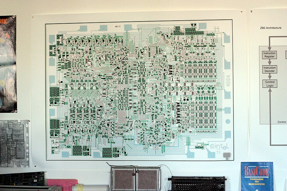 First commercial microprocessor (1971), showing how early ISAs were implemented in hardware. (Image: Wolfgang Stief from Tittmoning, Germany, CC0, via Wikimedia Commons)
Based on the TU BSc CSIT syllabus for Computer Hardware Design, unit 2.
Discussion
Loading…