Applied PhysicsUnit 68 min read
Electromagnetism: Fields, Forces & Induction
Unit 6 of Applied Physics explores the fundamental principles of electromagnetism—magnetic fields, Biot-Savart law, Ampère’s law, Faraday’s law, Lenz’s law, and electromagnetic induction—linking electric currents to magnetic effects and vice versa, with real-world applications in generators, motors, and wireless chargi
Core Concepts
Magnetic Fields and Forces
Magnetic Field (B): An invisible field around a magnet or moving charge that exerts forces on other magnets or charges. It is a vector field, meaning it has both magnitude and direction.
Key Definitions:
- Magnetic Field Lines: Imaginary lines that represent the direction and strength of a magnetic field. They emerge from the North pole and enter the South pole.
- Magnetic Force on a Current-Carrying Conductor: A conductor carrying current in a magnetic field experiences a force given by F = I (L × B), where:
- F = Force (N)
- I = Current (A)
- L = Length of the conductor (m)
- B = Magnetic field (T)
- × denotes the cross product (direction given by the right-hand rule).
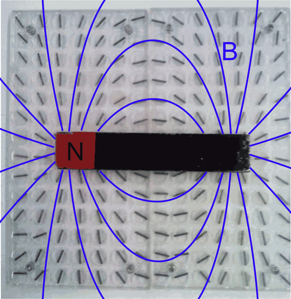 Shows field lines emerging from the North pole and entering the South pole. (Image: Original version:Yzarc-pan This version:Chetvorno, CC BY-SA 4.0, via Wikimedia Commons)
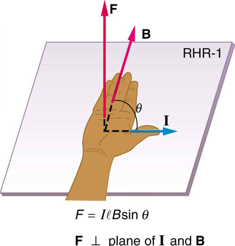 Illustrates how to determine the direction of the force using the right-hand rule. (Image: OpenStax, CC BY 4.0, via Wikimedia Commons)
Worked Example: Force on a Wire in a Magnetic Field
A wire of length 0.5 m carries a current of 3 A and is placed perpendicular to a magnetic field of 0.4 T. Calculate the force acting on the wire.
Solution: Using F = I (L × B), since the wire is perpendicular to the field, the angle θ = 90° and sin(90°) = 1. Direction: Use the right-hand rule to determine the direction of the force.
Biot-Savart Law and Ampère’s Law
Biot-Savart Law
Describes the magnetic field generated by a steady current. For a small current element Idl, the magnetic field dB at a point is given by:
- μ₀ = Permeability of free space (4π × 10⁻⁷ T·m/A)
- I = Current (A)
- dl = Infinitesimal length element (m)
- r = Distance from the current element to the point (m)
- r̂ = Unit vector pointing from the current element to the point
Ampère’s Law
Relates the magnetic field around a closed loop to the current passing through the loop:
- Useful for calculating magnetic fields in symmetric situations (e.g., solenoids, toroids).
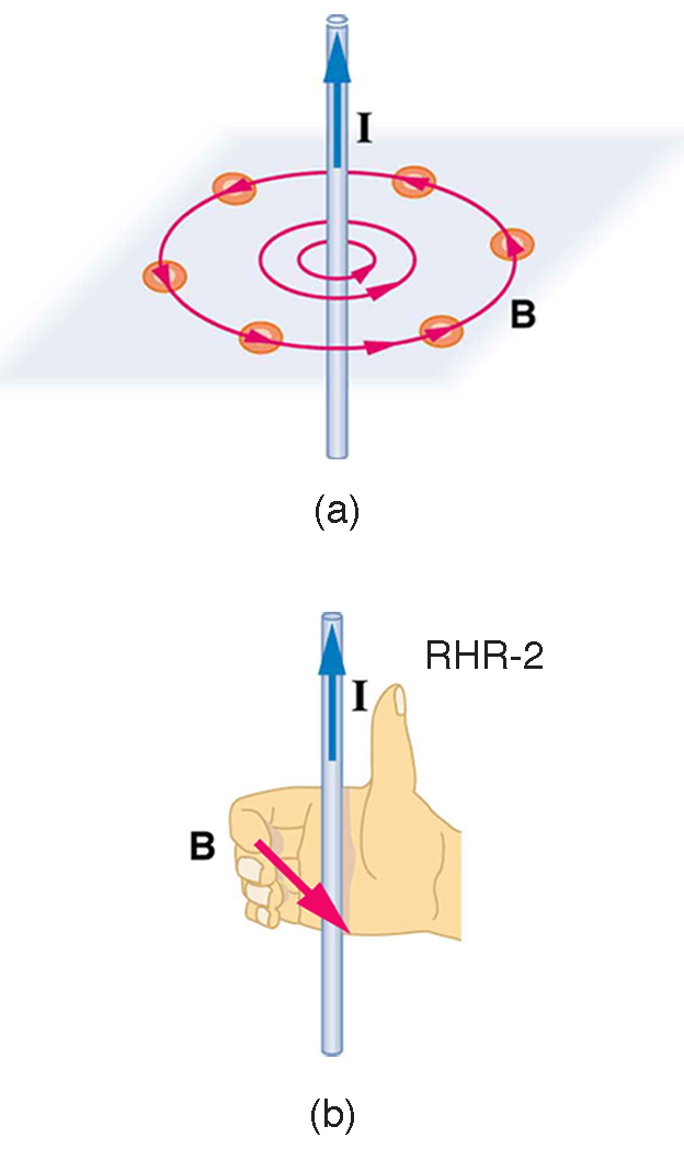 Shows circular field lines around the wire. (Image: OpenStax, CC BY 4.0, via Wikimedia Commons)
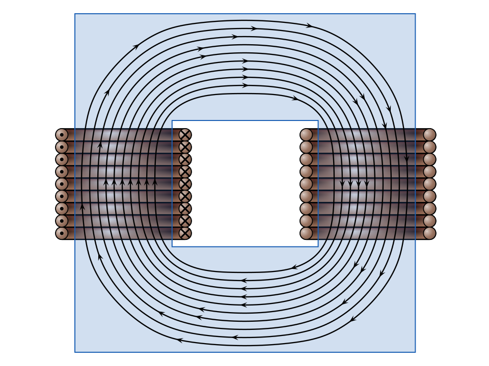 Illustrates how a solenoid creates a uniform magnetic field inside. (Image: MikeRun, CC BY-SA 4.0, via Wikimedia Commons)
Worked Example: Magnetic Field Inside a Solenoid
A solenoid has 500 turns/m and carries a current of 2 A. Calculate the magnetic field inside the solenoid.
Solution: Using Ampère’s law for a solenoid: where:
- n = Number of turns per unit length (500 turns/m)
- I = Current (2 A)
Faraday’s Law of Electromagnetic Induction
States that the induced electromotive force (emf) in a closed loop is equal to the negative rate of change of magnetic flux through the loop: where:
- Φ_B = Magnetic flux (T·m²)
- ε = Induced emf (V)
Magnetic Flux (Φ_B):
Lenz’s Law
The direction of the induced current is such that it opposes the change in magnetic flux that produced it.
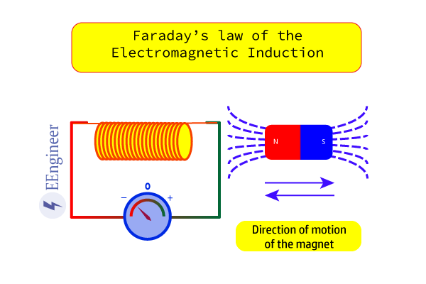 Shows a coil with changing magnetic flux inducing a current. (Image: Zahoornoman0, CC BY-SA 4.0, via Wikimedia Commons)
Worked Example: Induced EMF in a Loop
A rectangular loop of area 0.1 m² is placed in a magnetic field of 0.5 T. If the magnetic field is reduced to 0 T in 0.2 s, calculate the induced emf.
Solution: Change in magnetic flux: Rate of change of flux: Induced emf (magnitude): Direction: Use Lenz’s law to determine the direction of the induced current.
Applications of Electromagnetic Induction
Generators
Convert mechanical energy into electrical energy using Faraday’s law. A coil rotates in a magnetic field, inducing an alternating current (AC).
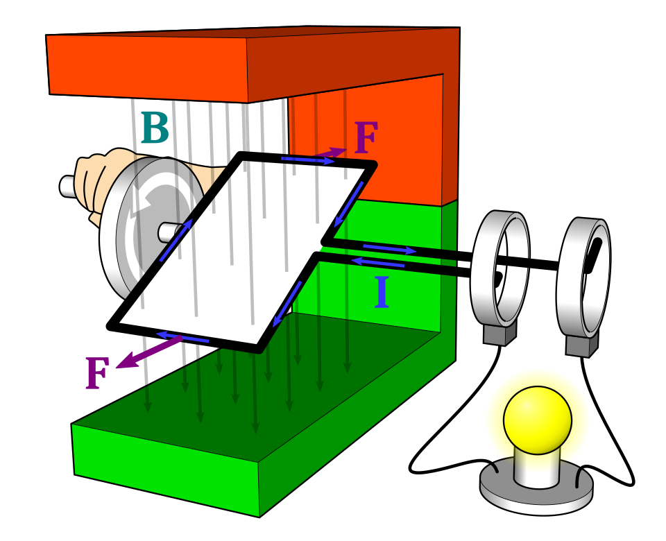 Shows how mechanical rotation induces AC in a coil. (Image: MikeRun, CC BY-SA 4.0, via Wikimedia Commons)
Transformers
Transfer electrical energy between circuits through electromagnetic induction. Consists of two coils (primary and secondary) wound around a common core.
Transformer Equation: where:
- V_p, V_s = Primary and secondary voltages
- N_p, N_s = Number of turns in primary and secondary coils
Worked Example: Transformer Voltage Calculation
A transformer has 200 turns in the primary coil and 1000 turns in the secondary coil. If the primary voltage is 220 V, calculate the secondary voltage.
Solution: Using the transformer equation:
In the Real World
Ncell and NTC (Nepal Telecommunications Company):
- Electromagnetic Induction in Wireless Charging: Modern smartphones (e.g., those using Ncell or NTC SIMs) support wireless charging via electromagnetic induction. A charging pad creates an alternating magnetic field, which induces a current in the phone’s receiver coil, converting magnetic energy into electrical energy to charge the battery.
eSewa and Khalti (Digital Payments):
- Magnetic Stripe Cards: Older versions of eSewa or Khalti payment cards used magnetic stripes that store data in tiny magnetic particles. When swiped, the magnetic field induces a current in the card reader, allowing data to be read and transactions to be processed.
Pathao and Daraz (Logistics and Delivery):
- Electric Motors in Delivery Vehicles: Pathao’s electric scooters and Daraz’s delivery vehicles use electric motors powered by batteries. These motors operate on the principle of electromagnetic induction, where an electric current in a coil interacts with a magnetic field to produce rotational motion, enabling efficient and eco-friendly deliveries.
Exam Tip
Memorize Key Equations:
- Magnetic force on a current-carrying conductor: F = I (L × B)
- Biot-Savart law and Ampère’s law for magnetic fields.
- Faraday’s law: ε = -dΦ_B/dt
- Transformer equation: V_p/V_s = N_p/N_s
Direction Matters:
- Always use the right-hand rule for magnetic forces and Lenz’s law for induced currents. Examiners often test your ability to determine directions correctly.
Real-World Applications:
- Relate theoretical concepts to real devices like generators, transformers, and electric motors. For example:
- In a Nepal Electricity Authority (NEA) power plant, turbines rotate coils in a magnetic field to generate electricity (Faraday’s law).
- Ncell’s base stations use transformers to step up or step down voltages for efficient power transmission.
- Relate theoretical concepts to real devices like generators, transformers, and electric motors. For example:
Graphical Questions:
- Be prepared to sketch magnetic field lines around current-carrying conductors, solenoids, and bar magnets. Label directions clearly.
Numerical Problems:
- Practice calculating magnetic forces, induced emfs, and transformer voltages. Always check units and significant figures.
Based on the PU BE Computer (PU) syllabus for Applied Physics, unit 6.
Discussion
Loading…