Applied PhysicsUnit 39 min read
Wave Optics – Interference, Young’s experiment, thin‑film & interferometers
Unit 3 of Applied Physics explains the principle of superposition, conditions for stable interference, classic experiments, mathematical treatment, and modern applications such as anti‑reflective coatings and interferometric sensors.
Key points
- Interference results from the superposition of coherent waves, producing alternating bright and dark regions.
- Stable interference requires monochromatic, coherent, and mutually coherent sources with a constant phase relationship.
- Young’s double‑slit experiment quantitatively relates fringe spacing to wavelength, slit separation, and screen distance.
- Thin‑film and multiple‑slit (diffraction‑grating) arrangements extend the basic principle to practical devices.
- Interferometers exploit path‑difference control for precision measurements in engineering and medicine.
1. Principle of Superposition
When two or more waves occupy the same region of space, the resultant displacement at any point is the algebraic sum of the individual displacements:
If the waves are sinusoidal with the same angular frequency and wave‑number ,
the resultant amplitude follows
where is the phase difference.
- Constructive interference: → .
- Destructive interference: → .
2. Conditions for Stable Interference
| Requirement | Why it matters | Typical laboratory realisation |
|---|---|---|
| Monochromaticity | Guarantees a single so fringe spacing is constant | Laser source (He‑Ne, diode) |
| Coherence | Fixed phase relationship over the observation time | Narrow‑band filter + short optical path difference |
| Spatial coherence | Wavefronts must be planar across the slits | Collimating lens or pinhole aperture |
| Temporal coherence | Path difference must be < coherence length | Use of lasers with > several meters |
3. Young’s Double‑Slit Experiment
Setup description
A monochromatic source illuminates a single narrow slit (to ensure spatial coherence). The emerging wave passes through two parallel slits separated by distance . On a screen placed at distance from the slits, an interference pattern of bright and dark fringes appears.
Mathematical derivation
Path difference between the two rays reaching a point on the screen at transverse coordinate :
Constructive condition: →
Fringe spacing (distance between successive bright fringes):
Worked example – Determining the wavelength of a red laser
A red diode laser ( unknown) shines on a double‑slit plate with . The screen is away. Measured distance between the 3rd‑order bright fringe () and the central maximum is .
Thus the laser emits greenish light, confirming the instrument’s calibration.
4. Multiple‑Slit (Diffraction Grating)
When many equally spaced slits (grating constant ) are used, the condition for principal maxima becomes
The intensity distribution sharpens with increasing number of slits ; the angular width of each principal maximum is approximately . Diffraction gratings are the heart of spectrometers and optical communication wavelength multiplexers.
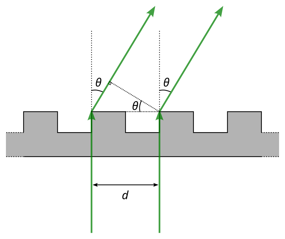 Close‑up of a ruled diffraction grating used in spectrometers (Image: Robert Thompson, CC BY-SA 4.0, via Wikimedia Commons)
5. Thin‑Film Interference
A thin transparent film (thickness , refractive index ) placed on a substrate produces reflected beams from the front and back surfaces. The optical path difference (OPD) between the two reflected rays is
where the extra term accounts for a phase reversal when reflection occurs from a medium of higher refractive index. Constructive interference (bright reflected colour) occurs when
and destructive interference (dark reflected colour) when
Real‑world example – anti‑reflective (AR) coating on smartphone screens. The coating thickness is chosen so that reflected waves from the air‑coating and coating‑glass interfaces destructively interfere for visible wavelengths, reducing glare.
6. Interferometers
6.1 Michelson Interferometer
Two perpendicular arms reflect light from a beam‑splitter. By moving one mirror by a distance , the optical path difference changes by . Each shift of one fringe corresponds to a path change of one wavelength:
Michelson interferometers are used for precise distance measurement, refractive‑index determination, and in gravitational‑wave detectors (LIGO).
6.2 Fabry‑Perot Interferometer
Consists of two partially reflecting parallel plates separated by distance . Multiple reflections produce sharp transmission peaks when
High‑resolution spectroscopy and laser cavity design rely on this principle.
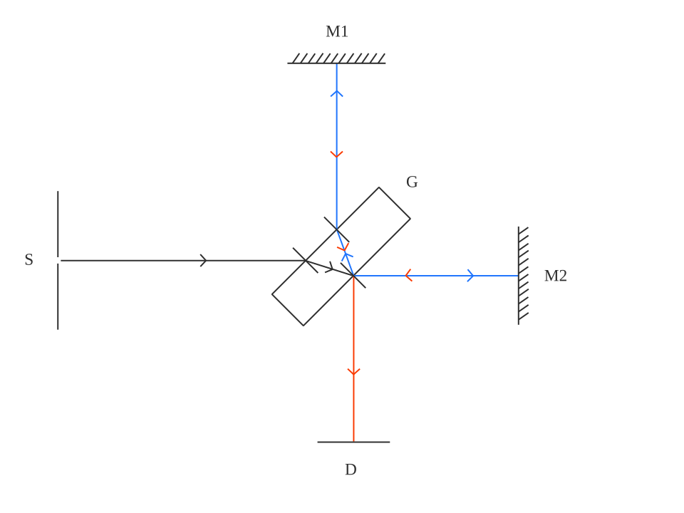 Classic Michelson interferometer used in laboratory optics (Image: Shivam Nilesh Shingade, CC BY-SA 4.0, via Wikimedia Commons)
7. Applications Overview
| Application | Interference principle used | How it works |
|---|---|---|
| Anti‑reflective coating (smartphone, glasses) | Thin‑film interference (destructive) | Film thickness ≈ cancels reflected light |
| Diffraction grating spectrometer | Multiple‑slit interference (constructive) | Grating separates wavelengths by angle |
| Optical fiber sensors (e.g., Ncell’s fiber‑optic temperature sensor) | Michelson/Fabry‑Perot interferometry | Changes in temperature alter optical path, shifting fringes |
| Holography | Record of interference between object and reference beams | Reconstructs 3‑D image when illuminated |
| Laser cavity | Standing‑wave interference between two mirrors | Only wavelengths satisfying round‑trip condition amplify |
8. Worked Example – Thin‑Film Coating for a Solar Panel
A solar panel glass is to be coated with an AR layer to minimise reflection at (peak solar spectrum). The coating material has . Required thickness for destructive interference at normal incidence:
Thus a 100 nm SiO₂ coating will reduce reflection by ≈ 90 % at 550 nm, increasing panel efficiency.
9. Comparison of Interference Set‑ups
| Feature                | Young’s Double‑Slit | Diffraction Grating | Thin‑Film Coating | Michelson Interferometer |
|------------------------|---------------------|---------------------|-------------------|--------------------------|
| Primary use            | Measuring λ, teaching concept | Spectroscopy, wavelength multiplexing | Reducing/controlling reflection | Precise distance/refractive index measurement |
| Number of apertures    | 2                   | 10⁴–10⁵ (grooves)   | 2 surfaces        | 2 arms (mirrors)         |
| Fringe visibility      | Moderate (depends on coherence) | Very sharp (high N) | Colour patterns (angle‑dependent) | High contrast, adjustable |
| Typical λ range        | Visible–UV          | UV–IR               | Visible           | Visible–IR               |
| Sensitivity to λ      | Linear (β ∝ λ)      | Linear (θ ∝ λ)      | Non‑linear (phase shift) | Direct (Δx = λ/2 per fringe) |
10. In the real world
Smartphone screen (e.g., iPhone, Samsung) – The glossy screen is coated with a multilayer thin‑film stack. Each layer’s thickness is engineered so that reflected light from the air‑film and film‑glass interfaces undergoes destructive interference for most visible wavelengths, giving a near‑zero‑glare display. The principle is exactly the thin‑film interference formula discussed above.
NEPSE (Nepal Stock Exchange) live‑ticker display – The high‑speed LED panels use diffraction‑grating based backlights to spread white light into a uniform white illumination. The grating’s constructive‑interference angles are chosen so that the dominant wavelengths overlap, producing a bright, colour‑balanced screen.
LIGO (Laser Interferometer Gravitational‑Wave Observatory) – Although not a Nepali institution, LIGO’s Michelson interferometer detects spacetime ripples by measuring minute changes in fringe position (as small as m). The same interferometric principle is taught in the lab for measuring tiny displacements, illustrating the extreme sensitivity achievable with interference.
11. Exam tip
- Memorise the three conditions for stable interference (monochromatic, coherent, spatially coherent) – they appear in many short‑answer questions.
- Derive the fringe‑spacing formula and be ready to plug numbers quickly; the exam often gives and and asks for .
- Thin‑film phase‑change rule: always add a term when the reflected ray comes from a higher‑index medium; forgetting this leads to sign errors.
- Interferometer fringe shift: remember that moving a mirror by shifts one fringe. This is a favourite quantitative problem.
- Diagram credit: draw a clean labelled diagram for Young’s experiment or Michelson interferometer; even a brief sketch earns marks for “illustration of principle”.
Based on the PU BE Computer (PU) syllabus for Applied Physics, unit 3.
Discussion
Loading…