Embedded SystemUnit 38 min read
Embedded Hardware Design: Boards, Interfaces & Power Systems
Unit 3 of Embedded System covers the core hardware components of embedded systems—microcontroller boards (Arduino, Raspberry Pi Pico), power supply circuits, clock generation, and peripheral interfaces (GPIO, ADC, PWM). It explains how to select components, design schematics, and troubleshoot hardware issues using real
Core Concepts in Embedded Hardware Design
Embedded hardware design is the bridge between software logic and physical implementation. It involves selecting the right microcontroller (MCU), designing power supply circuits, interfacing sensors/actuators, and ensuring reliable communication between components. This unit focuses on hardware architecture, component selection, and practical design principles for embedded applications.
1. Microcontroller Boards and Development Kits
Microcontroller boards are the heart of embedded systems. They integrate the MCU, memory, peripherals, and often debugging tools into a single package. Popular boards include:
- Arduino Uno (ATmega328P, 8-bit AVR)
- Raspberry Pi Pico (RP2040, dual-core ARM Cortex-M0+)
- STM32 Nucleo (ARM Cortex-M4/M7)
Key Components of a Microcontroller Board
classDiagram
    class MicrocontrollerBoard {
        +MCU Core
        +Flash Memory
        +SRAM
        +Peripherals (UART, SPI, I2C, ADC, PWM, GPIO)
        +Power Regulator
        +Debug Interface (SWD, JTAG)
    }
    class MCU {
        +Clock Source (Internal/External)
        +Interrupt Controller
        +Timers
    }
    MicrocontrollerBoard "1" --> "1" MCU : Contains
    MicrocontrollerBoard "1" --> "1..*" Peripheral : Includes
Comparison of Popular Boards
| Board | MCU | Clock Speed | Flash | SRAM | Key Features |
|---|---|---|---|---|---|
| Arduino Uno | ATmega328P (8-bit) | 16 MHz | 32 KB | 2 KB | Easy to use, large community |
| Raspberry Pi Pico | RP2040 (ARM Cortex-M0+) | 133 MHz | 2 MB | 264 KB | Dual-core, low power, USB OTG |
| STM32 Nucleo F4 | STM32F401 (ARM Cortex-M4) | 84 MHz | 1 MB | 192 KB | Floating-point unit, high performance |
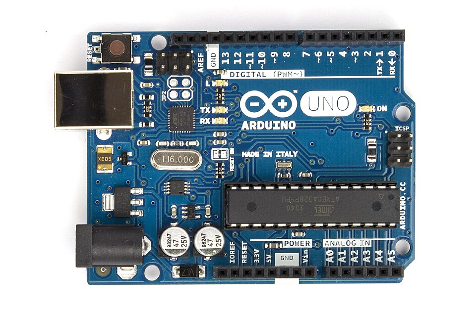 Arduino Uno board with labeled pins (ATmega328P, power pins, digital/analog I/O) (Image: oomlout, CC BY-SA 2.0, via Wikimedia Commons)
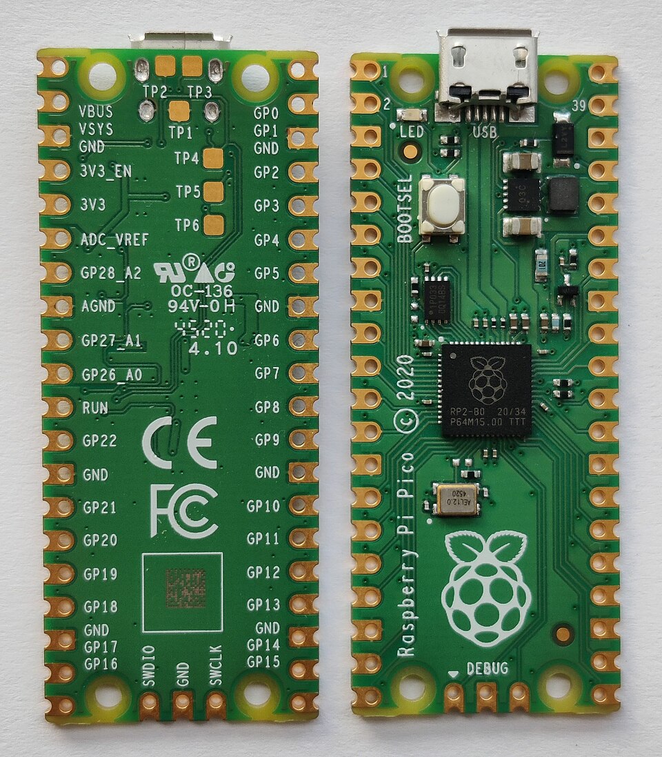 Raspberry Pi Pico with RP2040 MCU and USB connector (Image: Ogidya, CC BY-SA 4.0, via Wikimedia Commons)
How to Choose a Microcontroller Board?
- Performance Needs: Higher clock speed (e.g., STM32) for real-time tasks.
- Peripherals: Check if the board has required interfaces (e.g., SPI for sensors).
- Power Consumption: Low-power MCUs (e.g., ARM Cortex-M0) for battery-operated devices.
- Development Ecosystem: Arduino for beginners, STM32 for professionals.
Worked Example: Traffic Signal Controller
- Board: Arduino Uno (ATmega328P, 16 MHz)
- Peripherals: 3x relays (for red/yellow/green LEDs), 1x push button (pedestrian request)
- Why? Simple GPIO control, low cost, and easy programming.
2. Power Supply Design for Embedded Systems
Embedded systems require stable power to function reliably. Power supply design involves:
- Voltage Regulation (Linear vs. Switching Regulators)
- Battery Management (LiPo, Supercapacitors)
- Noise Filtering (Capacitors, Inductors)
Types of Power Supplies
mindmap
  root((Power Supply Types))
    Linear Regulator
      +Simple, low noise
      -Inefficient (heat loss)
    Switching Regulator
      +High efficiency (90%+)
      -Complex design, EMI noise
    Battery
      +Portable
      -Requires charging circuit
    USB Power
      +Standardized (5V, 9V)
      -Limited current
Linear vs. Switching Regulators
| Feature | Linear Regulator | Switching Regulator |
|---|---|---|
| Efficiency | Low (20-50%) | High (80-95%) |
| Noise | Low | High (requires filtering) |
| Cost | Low | Moderate (extra components) |
| Use Case | Audio circuits, sensors | Portable devices, high-power |
 Switching regulator (inductors, MOSFET, diode) (Image: TyIzaeL, Public domain, via Wikimedia Commons)
Worked Example: Portable Weather Station
- Power Source: 3.7V LiPo battery
- Regulator: LM2596 (3.3V buck converter)
- Why? High efficiency (92%) to extend battery life.
3. Clock Generation and Timing Circuits
The MCU clock determines processing speed. Clock sources include:
- Internal Oscillator (e.g., 8 MHz in ATmega328P)
- External Crystal (e.g., 16 MHz for Arduino)
- PLL (Phase-Locked Loop) for frequency multiplication
Clock Tree in an MCU
graph LR
    A["Crystal Oscillator"] --> B["PLL"]
    B --> C["System Clock"]
    C --> D["Peripheral Clocks"]
    C --> E["CPU Core"]
Worked Example: Real-Time Clock (RTC) Module
- Clock Source: 32.768 kHz crystal (common in RTCs like DS3231)
- Why? Low power consumption for timekeeping.
4. Peripheral Interfaces (GPIO, ADC, PWM, UART)
Peripherals extend the MCU’s functionality. Key interfaces:
- GPIO (General-Purpose Input/Output): Digital signals (buttons, LEDs).
- ADC (Analog-to-Digital Converter): Converts analog signals (sensors) to digital.
- PWM (Pulse-Width Modulation): Controls brightness (LEDs), motor speed.
- UART (Universal Asynchronous Receiver/Transmitter): Serial communication.
ADC Working Principle
sequenceDiagram
    participant Sensor as Analog Sensor
    participant ADC as ADC Module
    participant MCU as Microcontroller
    Sensor->>ADC: Analog Voltage (0-5V)
    ADC->>MCU: Digital Value (0-1023 for 10-bit ADC)
    MCU->>Display: Processed Data
Worked Example: Temperature Monitoring with LM35
- Sensor: LM35 (outputs 10 mV/°C)
- ADC: 10-bit (0-1023 → 0-5V)
- Calculation:
- If ADC reads 512, voltage =
- Temperature = (Error: LM35 max is 150°C → Check scaling!)
5. PCB Design Basics for Embedded Systems
Printed Circuit Boards (PCBs) physically connect components. Key steps:
- Schematic Design (Circuit diagram)
- Component Placement (Minimize trace lengths)
- Routing (Avoid crossovers, use ground planes)
- Gerber Files (For PCB manufacturing)
PCB Design Rules
mindmap
  root((PCB Design Best Practices))
    Trace Width
      +Thicker for high current
    Ground Plane
      +Reduces noise
    Via Placement
      +Avoid near sensitive signals
    Silkscreen
      +Component labels for assembly
Worked Example: Custom Sensor Node PCB
- Components: ATmega328P, BMP180 (pressure sensor), LiPo charger
- Design: Single-sided PCB (low cost), 0.5 mm trace width for 100 mA current.
In the Real World
eSewa (Nepal):
- Idea Used: UART Communication
- How? The backend server communicates with payment terminals (MCU + UART) to process transactions securely.
Pathao (Ride-Hailing App):
- Idea Used: GPS Module + MCU Interfacing
- How? The app’s driver app uses an ESP32 (MCU with GPS) to track real-time location and send data via Wi-Fi.
NTC Traffic Management System:
- Idea Used: Relay Control + Timer Circuits
- How? Traffic lights use an Arduino to sequence signals based on sensor inputs (vehicle detection via IR sensors).
Khalti POS Machine:
- Idea Used: ADC for Card Swipe Data + UART for Payment Processing
- How? The magnetic stripe reader outputs analog signals converted by the MCU’s ADC, then sent via UART to the payment gateway.
Exam Tip
- Board Selection: Always justify your choice (e.g., "STM32 for floating-point math in robotics").
- Power Calculations: Know how to compute current draw (e.g., ) and regulator efficiency.
- ADC Scaling: Remember to convert digital values to physical units (e.g., voltage, temperature).
- PCB Design: Expect questions on trace width, ground planes, and via usage.
- Real-World Applications: Relate theory to systems like traffic lights, medical devices, or IoT sensors.
Key Formulae to Memorize
- ADC Resolution: (e.g., 10-bit ADC with 5V ref → 4.88 mV/LSB)
- PWM Frequency: (where is the timer value)
- Power Dissipation (Linear Regulator):
Based on the PU BE Computer (PU) syllabus for Embedded System (ELX320), unit 3.
Discussion
Loading…